Anchor rod for an attachment anchor

a technology of anchor rod and anchor rod, which is applied in the direction of screws, dowels, building components, etc., can solve the problems of relatively high cost of anchor rod, and achieve the effect of reducing thread pitch, protecting against corrosion, and desired surface characteristics

Inactive Publication Date: 2000-02-29
HILTI AG
View PDF8 Cites 36 Cited by
  • Summary
  • Abstract
  • Description
  • Claims
  • Application Information

AI Technical Summary

Benefits of technology

The anchor rod according to the invention can be secured in the prepared receiving bore in a very simple way and without any additional auxiliary means. Simply, only a percussion drilling tool is needed, which is already available for forming the receiving bore. The anchor rod is inserted with its trailing end in a chuck of the percussion drilling tool. The setting of the anchor rod into the receiving bore with the already placed mortar sheath is effected by pushing the anchor rod into the receiving bore by drilling and percussion action.
The thread pitch of the coarse thread-like profile of the transporting section can diminish toward the compression section. Thereby, the transportation speed of the mixed mortar mass distributed over the anchoring region slows down toward the trailing end, whereby a certain pre-compression of the mortar mass takes place. This further assists the action of the compression section, and it insures that no flow of the mortar mass out of the receiving bore takes place and no soiling of the attachment section of the anchor rod occurs. The diminishing of the thread pitch in the direction of the compression section requires shortening of the cone-like regions of the transporting section. Also, the compression section can be provided with at least one cone-shaped region widening toward the free end. This cone promotes a secondary expansion behavior of the attachment anchor necessary for increasing the holding force, e.g., in torn concrete. The cutter at the free end is preferably formed by a wedge-shaped bevel of the head portion which extends up to the circumferential surface of the head portion. The cutter is suitable for breaking and comminution of both glass sheathes and foil sheathes in which mortar components are stored. Because the bevel extends relative to the anchor rod axis under an angle of about 45.degree., the axial impacts of the percussion drilling tool are particularly well transmitted to the sheath, and the sheath is comminuted during the rotation of the anchor rod, without blocking it. To provide for separation of the anchor rod and the mortar mass in case of fissures and to be able to expand the anchor rod further, the outer surface of the anchoring region is formed non-adhesive with respect to the organic and / or inorganic mortar mass. From the manufacturing point of view, it is advantageous when the outer surface of the anchoring region is galvanically bright nickel-plated. This manufacturing step can be economically integrated in series production. The anchor rod has the desired surface characteristics and is protected against corrosion.

Problems solved by technology

This attachment method is relatively expensive.

Method used


Image

  • Anchor rod for an attachment anchor
  • Anchor rod for an attachment anchor
  • Anchor rod for an attachment anchor

Examples


Embodiment Construction

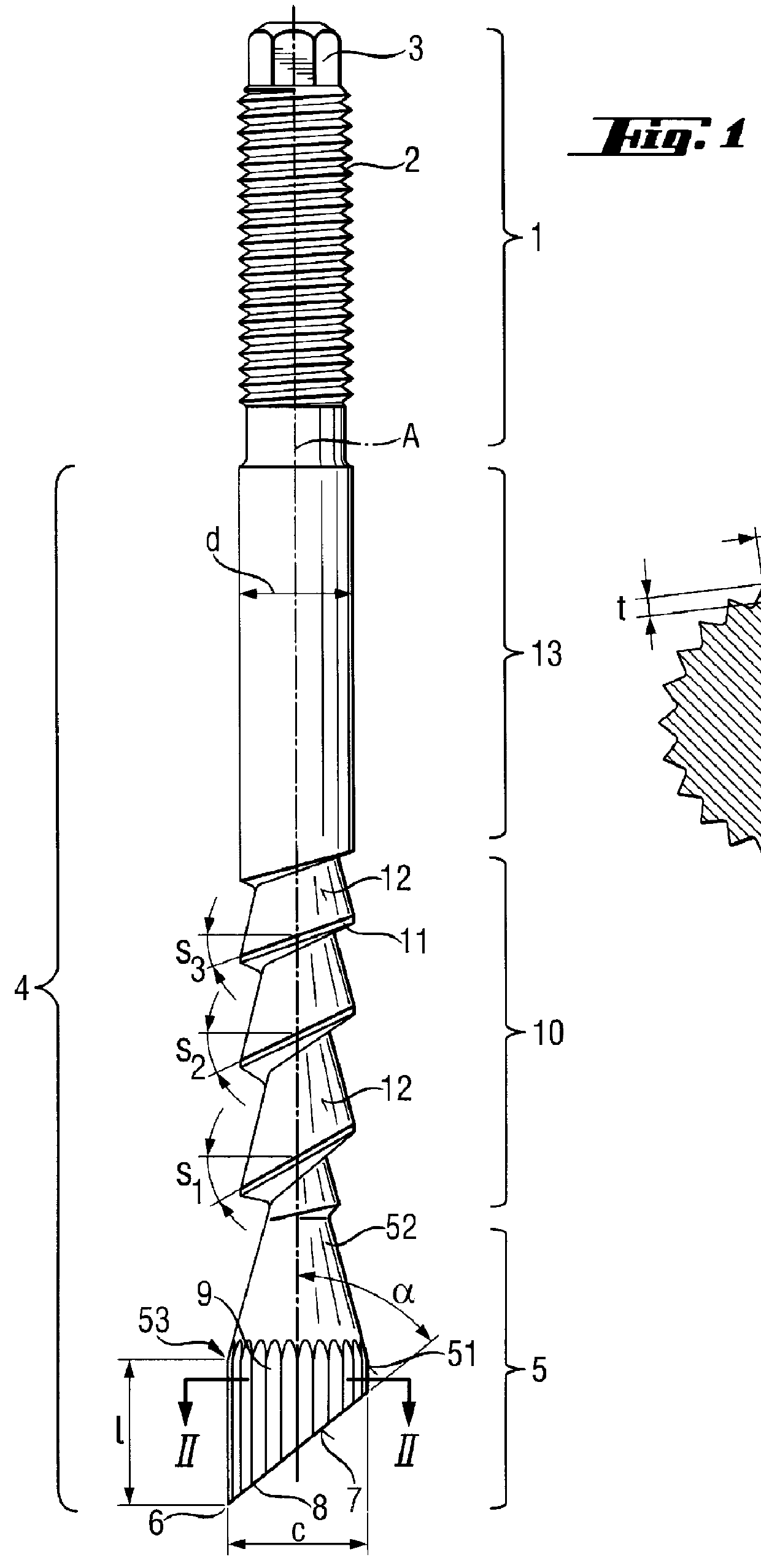
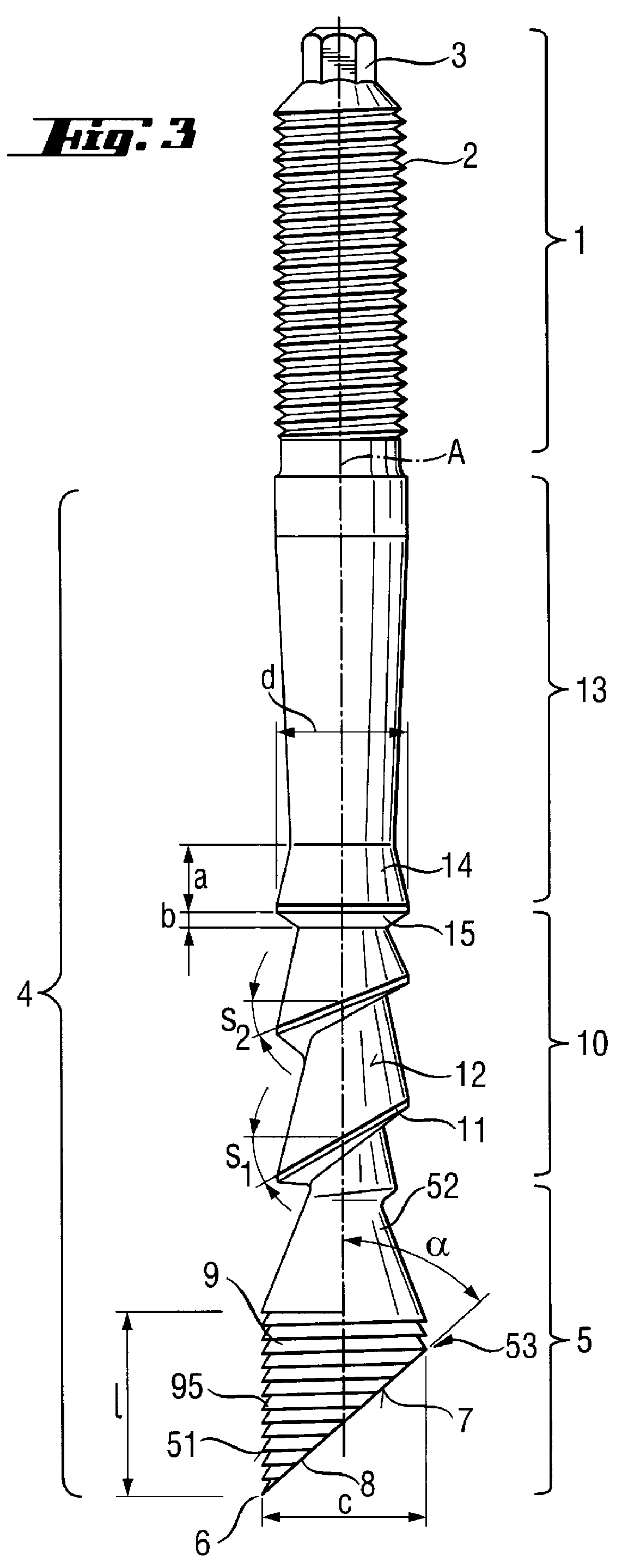
Exemplary embodiments of an anchor rod for an attachment anchor, and according to the present invention, which are shown in FIGS. 1 and 3, have a trailing attachment region 1 which is provided with an outer thread 2 forming load application means. The trailing end of the anchor rod which in a setting condition, as a rule, projects from a receiving bore, is formed as an attachment end 3, with which the anchor rod is inserted into a chuck of a rotary drilling tool (not shown), e.g., a hammer drill of the assignee of the present invention, for setting purposes. An anchoring region 4, which is put into a hardenable organic and / or inorganic mortar mass and, in a setting condition, is embedded in the hardened mortar mass, adjoins the attachment region 1.

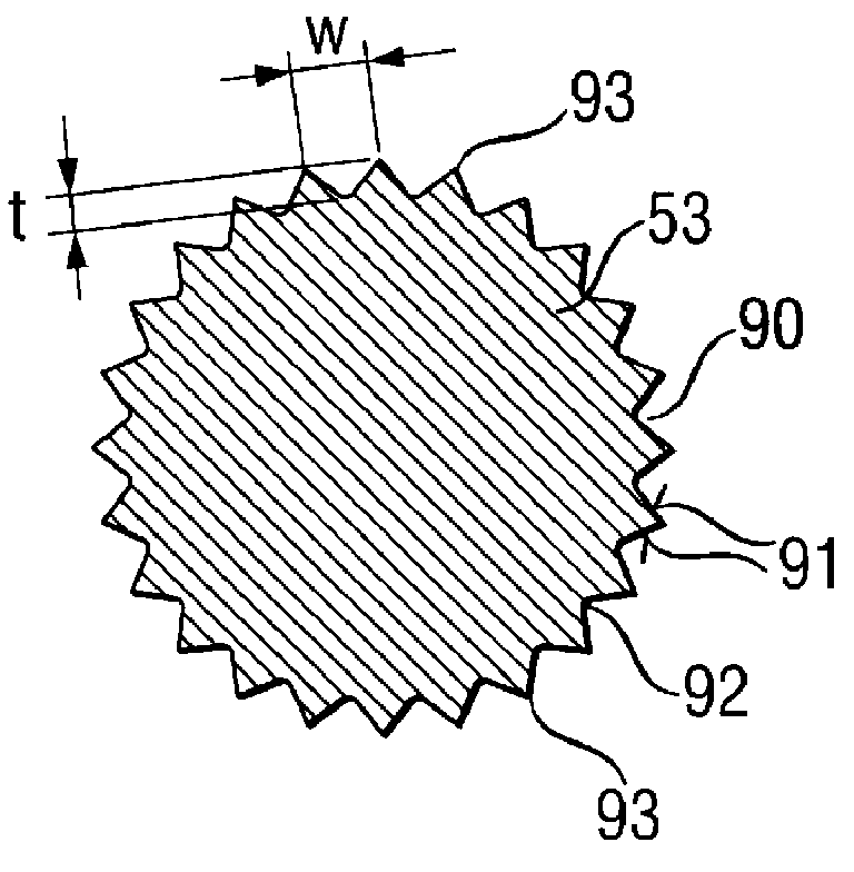
A frontmost section of the anchoring region 4, which is adjacent to the bore bottom, is formed as a mixing section and includes a head portion 5 at the free front end 6 of which a cutter 7, which extends somewhat transverse to the axis A o...


PUM


Abstract

An anchor rod for an attachment anchor including a trailing region (1) provided with a load application element (2), and an anchoring region (4) submergeable in a hardenable inorganic and/or organic mortar mass and having a mixing section formed of a head portion (5) provided at its free end (6) with a cutter (7) extending substantially transverse to the axis (A) of the anchor rod, a transporting section (10) adjoining the mixing section, and a compression section (13) adjoining the transporting section (10), with the head portion (5) having a region (53), the outer diameter (c) of which is larger than the largest diameter (d) of the transporting and compression sections (10,13) of the anchoring region (4), and provided with a mortar mass transporting arrangement (9).

Description

1. Field of InventionThe present invention relates to an anchor rod for an attachment anchor and which is secured with a hardenable organic and / or inorganic mortar mass in a receiving bore, includes an anchoring region and is provided with load application means.2. Description of the Prior ArtTwo anchoring methods proved themselves capable of providing a substantially expansion pressure-free attachment. One of the methods consists in that an anchor with expandable segments is secured in an undercut in the base of a receiving bore. The segments are swung out in the region of the undercut and retain the anchor axially by form-lockingly engaging the undercut. This attachment method is relatively expensive. First, a receiving bore needs to be formed, and then an undercut should be formed at a pre-determined depth of the receiving bore with a special tool. Only then, the anchor can be set into the receiving bore. The swinging of the retaining segments is effected, for example, by axially...

Claims


Application Information

Patent Timeline
Patent Type & Authority Patents(United States)
IPC IPC(8): F16B13/00F16B13/14F16B35/04E04B1/41
CPCF16B13/141
Inventor LEIBHARD, ERICHLUDWIG, WOLFGANG
Owner HILTI AG
Why Eureka
Try Eureka