Transmyocardial implant procedure and tools

a transmyocardial and implant technology, applied in the field of cardiac revascularization, can solve the problems of difficult manipulation of the vessel, difficulty in inserting the implant into the lumen of the coronary vessel, and uncontrolled flow of blood, and achieve the effect of facilitating the placement of the implan

Inactive Publication Date: 2000-02-29
HORIZON TECH FUNDING CO LLC
View PDF9 Cites 91 Cited by
  • Summary
  • Abstract
  • Description
  • Claims
  • Application Information

AI Technical Summary

Benefits of technology

According to a preferred embodiment of the present invention, a method and related tools are disclosed for forming a blood flow path from a heart chamber to a coronary vessel at an exterior surface of a heart wall. The method includes selecting a hollow conduit having a vessel portion and a myocardial portion. The vessel portion has an open leading end sized to be inserted into the coronary vessel. The myocardial portion has an open leading end. The myocardium portion is sized to extend through a thickness of the heart wall. The myocardial portion is placed in the heart wall with the open leading end of the myocardial portion protruding into the heart chamber. Blood flow through the conduit from the heart chamber is at least partially blocked. Blood flow through the conduit from the heart chamber is opened. The leading end of the vessel portion is placed in the coronary vessel. The tools of the invention include sheaths for temporarily surrounding the vessel and myocardial portions of the implant. The sheaths facilitate placement of the implant and are removed over the implant following placement.

Problems solved by technology

In addition to undesirable blood loss, the uncontrolled flow of blood can obscure a surgeon's field of vision.
Therefore, it is difficult to insert the implant into the lumen of the coronary vessel.
However, due to the small size of the vessel, restricted space for manipulating surgical tools, and the importance of avoiding damage to the coronary vessel, such a manipulation of the vessel is difficult.

Method used


Image

  • Transmyocardial implant procedure and tools
  • Transmyocardial implant procedure and tools
  • Transmyocardial implant procedure and tools

Examples


Embodiment Construction

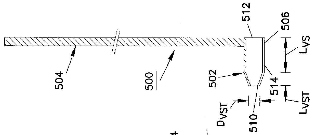
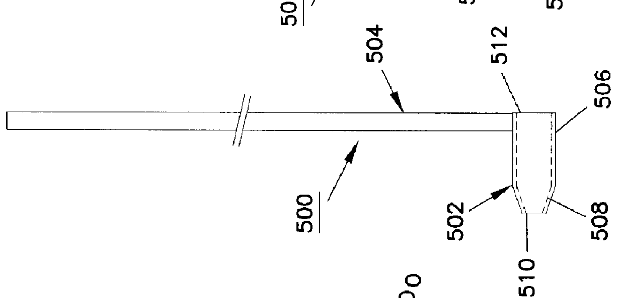
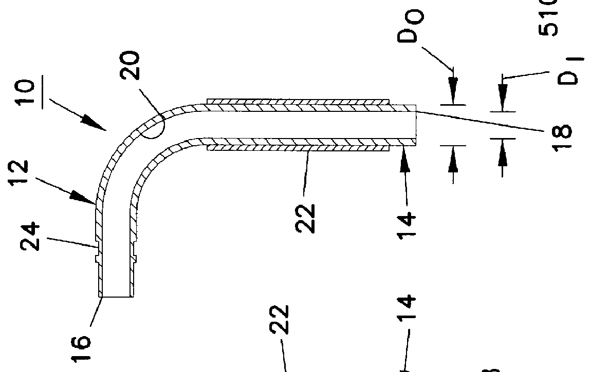
Referring now to the several drawing figures, in which identical elements are numbered identically throughout, a description of a preferred embodiment of the present invention will now be provided. Throughout the description, specific dimensions and materials of elements of the invention are given. Such specificity is presented to facilitate an understanding of the invention and is not intended to limit the scope of the claims appended hereto. For example, sizing of the elements is given to illustrate how the elements cooperatively fit together during the procedure of the invention. The procedure is described with reference to placement of a transmyocardial implant 10 between a coronary artery 82 and a left ventricle 86. It will be appreciated the invention is applicable to the formation of a direct blood flow path between a heart chamber (left or right ventricle or atrium) and a coronary vessel (artery or vein). Further, vessel size and myocardium thickness vary throughout the hear...


PUM


Abstract

A blood flow path is formed from a heart chamber to a coronary vessel on an exterior surface of a heart wall. A hollow conduit has a vessel portion and a myocardial portion. The vessel portion has an open leading end sized to be inserted into the coronary vessel. The myocardial portion has an open leading end and the myocardium portion is sized to extend through a thickness of the heart wall. The myocardial portion is placed in the heart wall with the open leading end of the myocardial portion protruding into the heart chamber. Blood flow through the conduit from the heart chamber is at least partially blocked. The leading end of the vessel portion is placed in the coronary vessel. Blood flow through the conduit from the heart chamber and into the vessel is then opened.

Description

I. BACKGROUND OF THE INVENTION1. Field of the InventionThe present invention pertains to cardiac revascularization and more particularly to a procedure for cardiac revascularization and related tools for forming a blood flow path through a heart wall from a heart chamber to a coronary vessel.2. Description of the Prior ArtCommonly assigned and co-pending U.S. patent application Ser. No. 08 / 882,397 filed Jun. 25, 1997, entitled "Method and Apparatus for Performing Coronary Bypass Surgery", and filed in the name of inventors Mark B. Knudson and William L. Giese, teaches an implant for defining a blood flow conduit directly from a chamber of the heart to a lumen of a coronary vessel. The text of the '397 application has been published on Feb. 25, 1998 in corresponding UK Patent Application GB 2 316 322 A. An embodiment disclosed in the aforementioned application teaches an L-shaped implant in the form of a rigid conduit. The conduit has one leg sized to be received within a lumen of a ...

Claims


Application Information

Patent Timeline
Patent Type & Authority Patents(United States)
IPC IPC(8): A61F2/06A61F2/02A61F2/94
CPCA61F2/2493A61F2/94Y10S623/904A61F2220/0008
Inventor VANNEY, GUY P.ODLAND, THOMAS L.SOLIEN, ERIC E.
Owner HORIZON TECH FUNDING CO LLC
Why Eureka
Try Eureka