Flexible tissue ablation elements for making long lesions

a flexible, tissue technology, applied in the field of tissue ablation systems and methods, can solve the problems of difficult introduction of large electrodes into the heart, difficulty in intimate contact with heart tissue, and merely providing "bigger" electrodes

Inactive Publication Date: 2000-02-29
EP TECH
View PDF17 Cites 210 Cited by
  • Summary
  • Abstract
  • Description
  • Claims
  • Application Information

AI Technical Summary

Problems solved by technology

Merely providing "bigger" electrodes does not meet this need.
Catheters carrying large electrodes are difficult to introduce into the heart and difficult to deploy in intimate contact with heart tissue.
FIG. 14 is a side view of an ablation element carrying individual coil electrodes that are not sufficiently flexible to conform to the desired curve of the element, causing gaps in tissue contact.
Without intimate contact along the entire length of the element 10, transmission of radio frequency energy lacks uniformity, thus resulting in undesired gaps in lesion p

Method used


Image

  • Flexible tissue ablation elements for making long lesions
  • Flexible tissue ablation elements for making long lesions
  • Flexible tissue ablation elements for making long lesions

Examples


Embodiment Construction

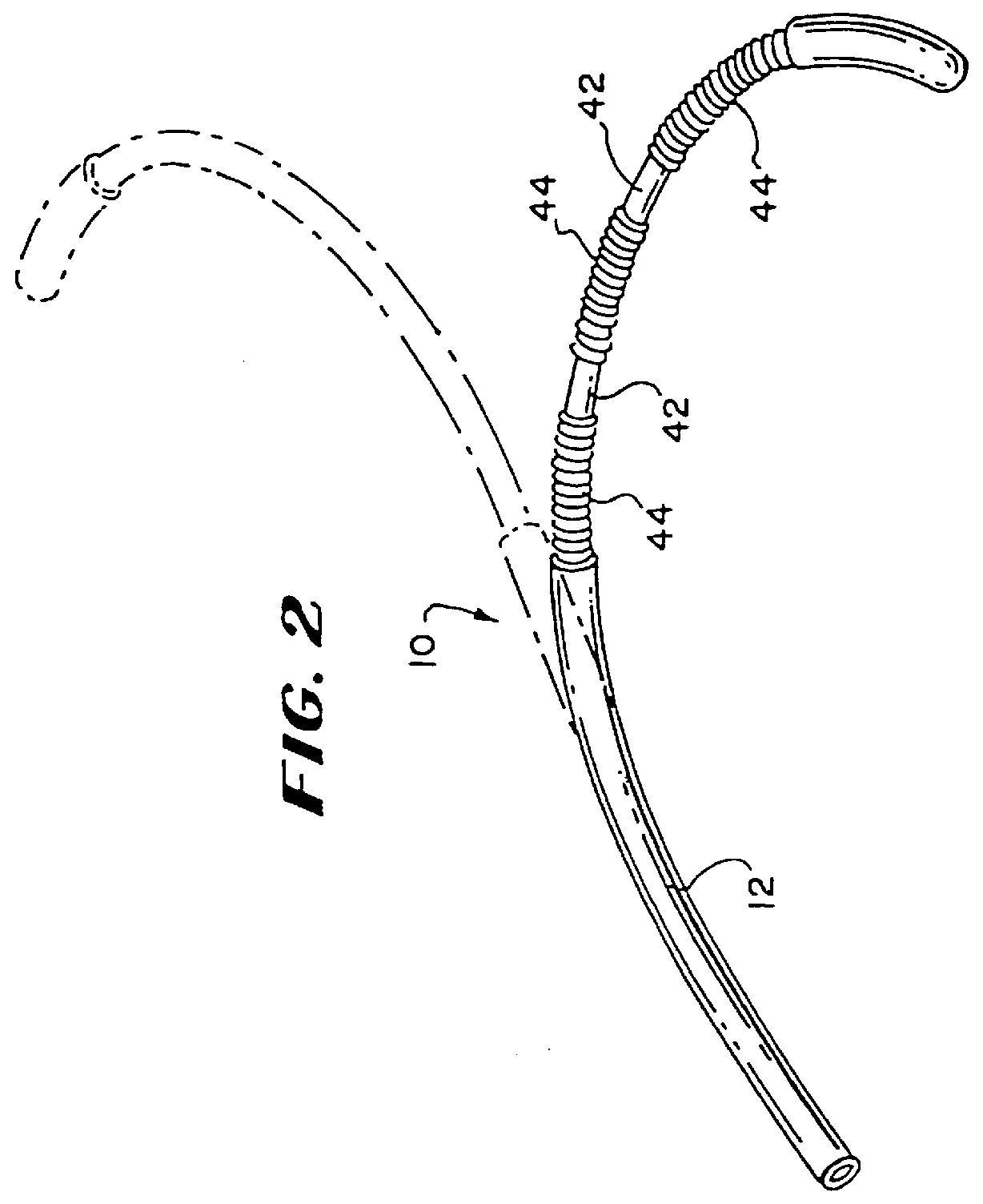
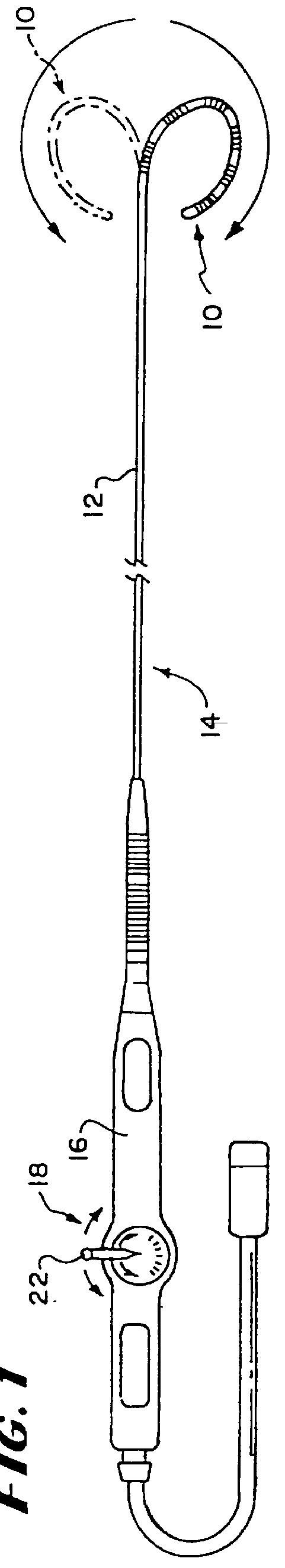
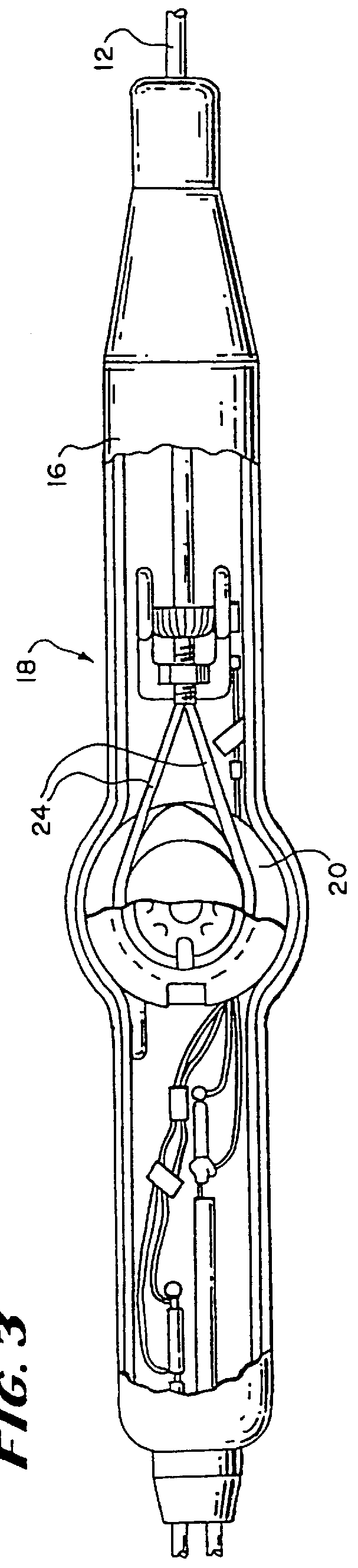
Four flexible ablation elements 10 were built for comparison, designated elements E1, E2, E3, and E4. Each ablation element E1-4 comprised six coil electrodes, each coil electrode being 12.5 mm in length. The coil electrodes were spaced apart by 2 mm. Each ablation element E1-4 used the same steering mechanism, as generally shown in FIGS. 3 and 4 and as earlier described.

The coil electrodes in ablation elements E1 and E2 used round wire having an outside diameter of 0.012 inch. In E1, the windings were adjacent, as represented by coil electrode 44(a) in FIG. 5. In E2, the windings were spaced apart, as represented by electrode 44(C) in FIG. 7. In E2, the distance D that the coil electrodes were spaced apart was 1 / 2 of the width of the wire, designated by the letter W in FIG. 7 (i.e., D=1 / 2W).

Ablation elements E3 and E4 used flat wire, 0.020 inch wide and 0.005 inch high. In E3, the windings were adjacent, as represented by electrode 44(b) in FIG. 5. In E4, the windings were spaced a...


PUM

PropertyMeasurementUnit
Lengthaaaaaaaaaa
Lengthaaaaaaaaaa
Lengthaaaaaaaaaa

Abstract

Devices and methods for ablating body tissue. The devices include a support body and at least one elongated electrode. Adjacent windings are spaced apart to impart enhanced flexibility to the elongated electrode.

Description

1. Field of the InventionsThe inventions relate to systems and methods for ablating tissue such as, for example, systems and methods for ablating myocardial tissue for the treatment of cardiac conditions.2. Description of the Related ArtPhysicians make use of catheters and other devices today in medical procedures to gain access into interior regions of the body to ablate targeted tissue areas. It is important for the physician to be able to precisely locate the device, and control its emission of energy within the body during tissue ablation procedures.For example, in electrophysiological therapy, ablation is used to treat cardiac rhythm disturbances. During some of these procedures, a physician steers a catheter through a main vein or artery into the interior region of the heart that is to be treated. The physician places an ablating element carried on the catheter near the cardiac tissue that is to be ablated. The physician directs energy from the ablating element to ablate the t...

Claims


Application Information

Patent Timeline
IPC IPC(8): A61B18/14A61B5/042A61B5/0408A61N1/06A61N1/05A61N1/40G01K1/00G01K1/02G01K3/14G01K3/00A61B18/00A61B17/00
CPCA61B5/0422A61B5/6858A61B18/1492A61N1/056A61N1/06A61N1/40G01K1/026G01K3/14A61B2017/00088A61B2017/00092A61B2017/0088A61B2018/00083A61B2018/00107A61B2018/00148A61B2018/0016A61B2018/00791A61B2018/1435A61B5/287
Inventor FLEISCHMAN, SIDNEY D.THOMPSON, RUSSELL B.PANESCU, DORINSWANSON, DAVID K.
Owner EP TECH
Why Eureka
Try Eureka