Antenna pattern measurement method and device

a technology of antenna pattern and measurement method, which is applied in the direction of wireless communication services, wireless communication services, transmission, etc., can solve the problems of large site, difficult to perfect, and use accurate but expensive means

Inactive Publication Date: 2000-02-29
CENT NAT DETUD SPATIALES C N E S
View PDF2 Cites 32 Cited by
  • Summary
  • Abstract
  • Description
  • Claims
  • Application Information

AI Technical Summary

Problems solved by technology

A positioner 13 rotates the antenna 10 to be measured in different directions, for example in rotation .phi. and in sighting direction .theta.. The disadvantage of this type of measurement base is that it requires a large site, the size of which depends on the wave length.
The disadvantage of this type of base is that uses accurate but expensive means, and furthermore which are more difficult to perfect.
The disadvantage of this type of base is that very accurate and very precise measurement probes and sophisticated computer facilities are necessary.

Method used


Image

  • Antenna pattern measurement method and device
  • Antenna pattern measurement method and device
  • Antenna pattern measurement method and device

Examples


Embodiment Construction

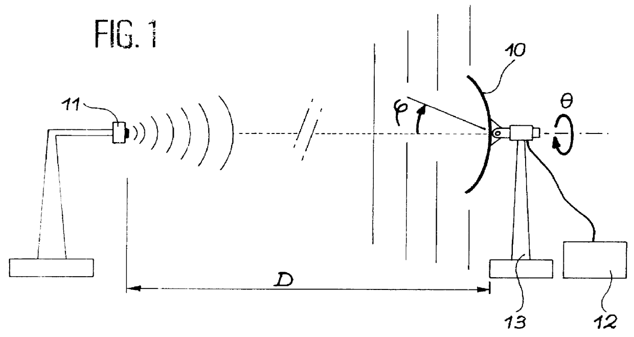
This invention proposes a process for measuring an antenna diagram in which:

The antenna is connected to a receiver capable of outputting measurements of the C / No ratio, which is the ratio of the useful signal power to the noise power spectral density. This receiver can also optionally measure the phase variation of the received signal carrier.

The antenna is placed at the top of a mast, or on a carrier satellite facing towards the sky to observe the satellites in a constellation, the antenna reception band containing the transmission band of the satellite antennas used.

The C / No ratios associated with observable satellites are automatically recorded for a given period.

The diagram for the said antenna is determined by calculation.

Advantageously, an antenna gain function can be calculated, making use of a limited number of coefficients. These coefficients are adjusted using measurements based on a least squares criterion.

For example, the antenna gain could be given by the following form...


PUM


Abstract

PCT No. PCT / FR96 / 01490 Sec. 371 Date Aug. 27, 1998 Sec. 102(e) Date Aug. 27, 1998 PCT Filed Sep. 24, 1996 PCT Pub. No. WO97 / 12253 PCT Pub. Date Apr. 3, 1997This invention relates to a process for measuring an antenna diagram in which: the antenna (30) is connected to a receiver (33) capable of supplying C / No measures (the ratio of the useful signal power to the noise power spectral density) and possibly phase variation measurements; the antenna (30) is placed at the end of a mast (32) or a carrier satellite facing towards the sky to track the satellites in a constellation, the antenna reception band being included in the satellite antenna transmission band; the C / No ratio and phase variations are automatically recorded for a given period; the diagram for the said antenna is deduced by calculation.

Description

This invention relates to a process and device for measuring an antenna diagram.STATE OF PRIOR ARTMeasurement methods are necessary to characterize antennas in order to:use experimental methods to size antennas that cannot be modeled;finalize the design of antennas that have already been designed by "approximate" models;validate the results of modeling obtained with "exact" software, and use these models when there is a doubt about the physical meaning of some of the calculation results.The purpose of the measurement equipment is to record the antenna radiation and matching characteristics:by reproducing actual usage conditions (for example plane waves in reception) as accurately as possible, by using long external bases (far field) or compact bases (plane wave recreated at short distance in an anechoic chamber);by precise readings of the near field (amplitude and phase) on a surface surrounding the antenna and by calculating the radiated far field;by impedance measurements (antenna...

Claims


Application Information

Patent Timeline
Patent Type & Authority Patents(United States)
IPC IPC(8): G01R29/10
CPCG01R29/10
Inventor ISSLER, JEAN-LUC
Owner CENT NAT DETUD SPATIALES C N E S
Why Eureka
Try Eureka