Integrated narrowband optical filter based on embedded subwavelength resonant grating structures

a narrowband optical filter and subwavelength resonant technology, applied in the direction of optical waveguide light guide, optical elements, instruments, etc., can solve the problem of limited current integrated narrowband optical filter

Inactive Publication Date: 2000-03-07
LOCKHEED MARTIN ENERGY SYST INC
View PDF8 Cites 229 Cited by
  • Summary
  • Abstract
  • Description
  • Claims
  • Application Information

AI Technical Summary

Problems solved by technology

(1-3) Current integrated narrowband optical filters are limited by their size in the density of devices that can b

Method used


Image

  • Integrated narrowband optical filter based on embedded subwavelength resonant grating structures
  • Integrated narrowband optical filter based on embedded subwavelength resonant grating structures
  • Integrated narrowband optical filter based on embedded subwavelength resonant grating structures

Examples


Embodiment Construction

The present invention and the various features and advantageous details thereof are explained more fully with reference to the nonlimiting embodiments that are illustrated in the accompanying drawings and detailed in the following description. Descriptions of well known components and processing techniques are omitted so as to not unnecessarily obscure the present invention in detail.

1. System Overview

A grating structure according to the present invention is confined within a waveguide. As an integrated optical device, the invention can be simple and compact. The invention can also be utilized to implement data processing methods that transform the signals being propagated in the waveguide so as to actuate interconnected discrete hardware elements, such as, for example, switching interconnected routers.

2. Detailed Description of Preferred Embodiments

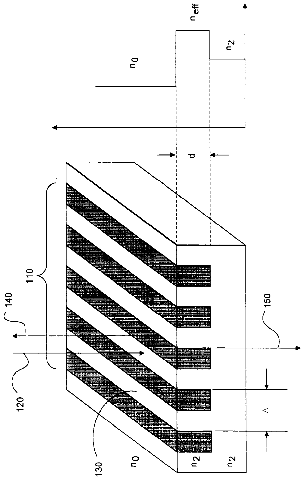
Referring to FIG. 1, a subwavelength grating structure 110 is shown. A subwavelength grating structure is a zeroth order diffraction gr...


PUM


Abstract

A resonant grating structure in a waveguide and methods of tuning the performance of the grating structure are described. An apparatus includes a waveguide; and a subwavelength resonant grating structure embedded in the waveguide. The systems and methods provide advantages including narrowband filtering capabilities, minimal sideband reflections, spatial control, high packing density, and tunability.

Description

1. Field of the InventionThe present invention relates generally to the field of grating structures. More particularly, the present invention relates to subwavelength grating structures. Specifically, a preferred implementation of the present invention relates to subwavelength resonant grating structures that are embedded in a waveguide. The present invention thus relates to embedded optical gratings of the type that can be termed embedded.2. Discussion of the Related ArtHistorically, subwavelength resonant grating structures have only been large planar surfaces..sup.(1-3) Current integrated narrowband optical filters are limited by their size in the density of devices that can be produced, their overall performance, and their ability to be actively altered for tuning and modulation purposes.Within this application several publications are referenced by superscripts composed of arabic numerals within parentheses. Full citations for these, and other, publications may be found at the ...

Claims


Application Information

Patent Timeline
IPC IPC(8): G02F1/01G02F1/035G02B5/20G02B6/124G02B6/12G02B5/18
CPCG02B5/1809G02B5/203G02B6/12007G02B6/124G02F1/035G02B2006/12107G02B2006/12109G02F2201/307G02F2203/055
Inventor GRANN, ERIC B.SITTER, JR., DAVID N.
Owner LOCKHEED MARTIN ENERGY SYST INC
Why Eureka
Try Eureka