Power cutter and centrifugal clutch for a power cutter

a centrifugal clutch and power cutter technology, which is applied in the direction of portable power-driven tools, metal sawing accessories, manufacturing tools, etc., can solve the problem that the dust suction-discharge fan is likely to be incapable of exhibiting sufficient dust suction-discharge performan

Inactive Publication Date: 2000-03-21
KIORITZ
View PDF2 Cites 34 Cited by
  • Summary
  • Abstract
  • Description
  • Claims
  • Application Information

AI Technical Summary

Problems solved by technology

Accordingly, the dust suction-discharge fan is likely to be incap

Method used


Image

  • Power cutter and centrifugal clutch for a power cutter
  • Power cutter and centrifugal clutch for a power cutter
  • Power cutter and centrifugal clutch for a power cutter

Examples


Embodiment Construction

In the following, a preferred embodiment of the present invention is described with reference to the accompanying drawings.

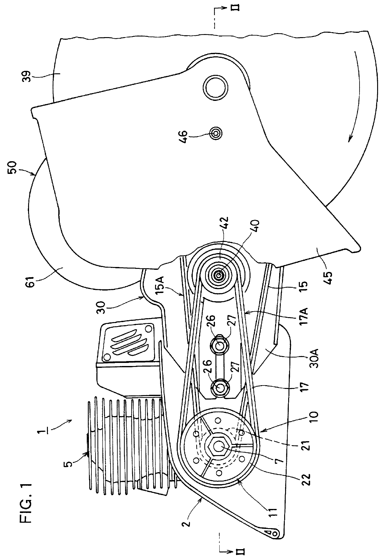
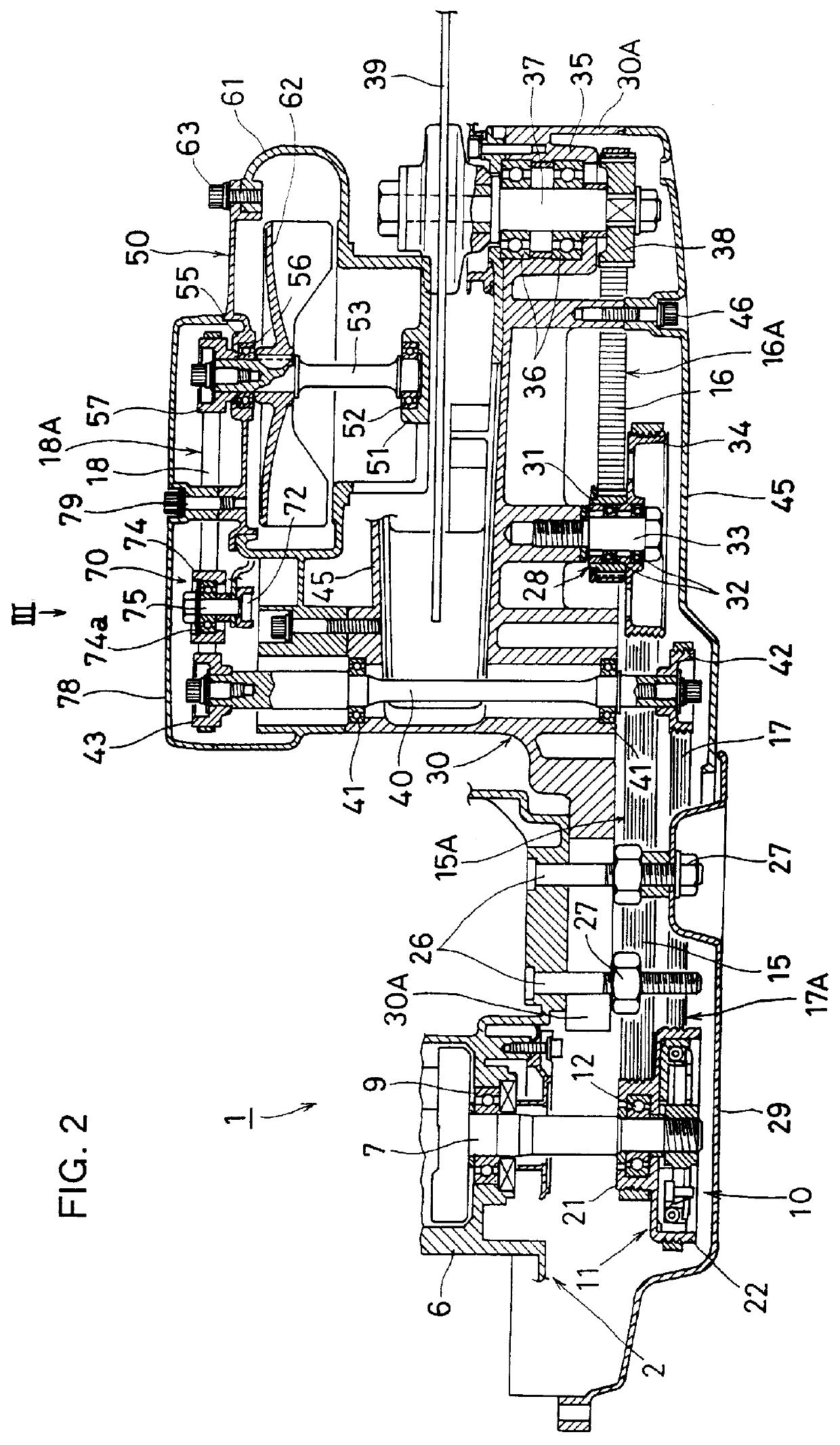
FIGS. 1 and 2 show a main part of an embodiment of a so-called engine-operated cutter as the portable power cutter according to the present invention, in which a handle frame, etc. are not shown.

The engine-operated cutter 1 as shown in FIGS. 1 and 2 includes a frame 2 and a small air-cooled two-cycle gasoline engine (hereinafter referred to simply as an engine) 5 as a prime mover approximately centrally disposed on the frame 2. Although not shown, a rear handle provided with a throttle trigger or the like is attached to the frame 2 at the back thereof and a front handle is so mounted on the frame 2 as to extend upward and forward from a lower center position thereof.

The engine 5 includes a crank case 6 and a crank shaft 7 journal-supported by the crank case 6 via ball bearings 9 (see FIG. 2). A centrifugal clutch 10, of conventional structure, is provided on the...


PUM

PropertyMeasurementUnit
Currentaaaaaaaaaa
Currentaaaaaaaaaa
Currentaaaaaaaaaa

Abstract

A power cutter is disclosed whose dust suction-discharge fan is driven to rotate at a high speed to thereby attain sufficient dust suction-discharge performance, and which can be constructed relatively compactly in size as a whole at a reduced cost. The power cutter includes two rotating operative components (30, 50) driven by a prime mover (5) and a centrifugal clutch (10) operatively connected to the output shaft (7) of the prime mover (5) for rotationally driving the two rotating operative components (30, 50). The centrifugal clutch (10) includes a clutch drum (11) composed integrally of a small diameter pulley portion (21) and a large diameter pulley portion (22). Belt-type drive trains (15A, 16A and 17A, 18A) transmit the rotational drive force to the rotating operative components (30, 50), respectively.

Description

1. Field of the InventionThe present invention relates to a portable power cutter having two rotating operative components rotationally driven by a prime mover such as a small air-cooled two-cycle gasoline engine or an electric motor. More particularly, the invention relates to a power transmission mechanism for a portable power cutter having, as the rotating operative components, an operative cutter (having cutting means such as a cutter blade) and a dust suction-discharge fan for discharging the dust resulting from the cutting operation.2. The Prior ArtIn prior art portable power cutters of this type, there has heretofore been proposed and used a body or frame carrying a prime mover, an operative cutter including cutting means, such as a cutter blade, a safety cover, etc., and a dust suction-discharge fan for discharging by sucking the dust resulting from use of the cutting means on concrete-formed material or the like.In such conventional portable power cutters, the cutting means...

Claims


Application Information

Patent Timeline
IPC IPC(8): B23D59/00B23D47/12B23D47/00B23Q11/00B28D1/04F16D43/14
CPCB23D47/12B23D59/006B23Q11/0046
Inventor TAOMO, TOSHIOSONG, WANG YAN
Owner KIORITZ
Why Eureka
Try Eureka