Pilot operated pressure valve

a technology of pressure valve and pilot, which is applied in the direction of fluid pressure control, process and machine control, instruments, etc., can solve the problems of excessively abrupt energizing of the hydraulic motor, operation detrimental, and equipment being operated will exhibit too sharp start-up

Inactive Publication Date: 2000-03-21
SUN HYDRAULICS LLC
View PDF2 Cites 43 Cited by
  • Summary
  • Abstract
  • Description
  • Claims
  • Application Information

AI Technical Summary

Problems solved by technology

When the hydraulic system is actuated so as to energize a hydraulic actuator, cylinder or motor, pressure increases virtually instantaneously As a result, there is a sharp hydraulic spike in the pressure level of the fluid system which results in excessively abrupt energizing of the hydraulic motor.
Not only is this operational limitation abusive to the system, but it may also be operationally detrimental in that the equipment being operated will exhibit too sharp a start-up.
A general technical problem with the above relief valves concerns the principal embodied in each that depends upon a very high pressure drop across a pilot orifice which varies somewhat proportional to inlet pressure.
However, the flow across such arrangements is viscosity sensitive.
The friction of the moveable

Method used


Image

  • Pilot operated pressure valve
  • Pilot operated pressure valve
  • Pilot operated pressure valve

Examples


Embodiment Construction

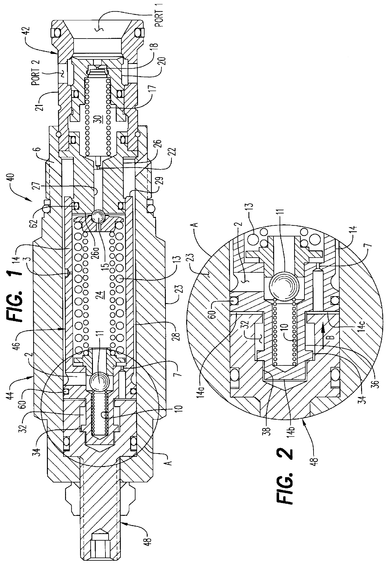
If the pressure at port 1 is 3000 p.s.i., a pilot flow will pressurize the pilot chamber 24 to 110 p.s.i. (110 p.s.i. times effective area 0.172=18.9 lbs., 18.9 lbs. / 0.0066 square inch (effective area of the pilot ball) is 2890 p.s.i. plus 110 p.s.i. is 3000 p.s.i., a pressure ratio of about 27 to 1.

PERFORMANCE CURVES

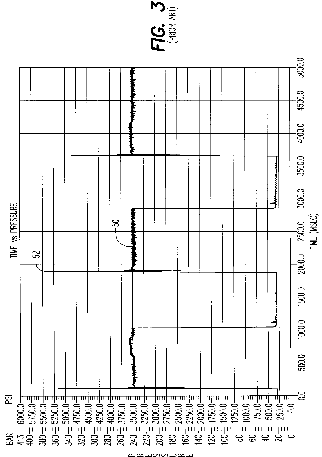
Referring now to FIG. 3, a typical prior art pressure relief valve without the soft start mechanism was actually tested. The operating pressure of the valve is shown at 50 to be approximately 3500 p.s.i. That amount of fluid pressure was repeatedly introduced into the inlet port of the prior art valve, the system pressure being recorded over time shown in milliseconds. The typical damaging hydraulic pressure spike which occurred virtually instantaneously at the start of each pressure cycle is shown at 52 reaching as high as about 5400 p.s.i., over fifty percent (50%) greater than the intended operating pressure of the prior art valve.

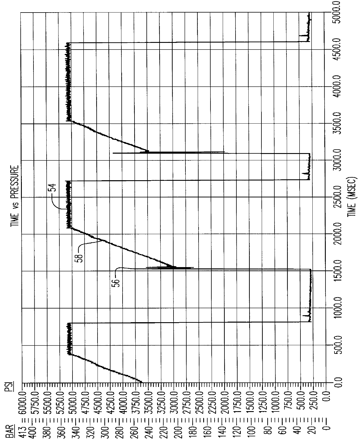
The present invention was subjected ...


PUM


Abstract

A pilot operated pressure valve which limits the rate of pressure rise and substantially eliminates excessive system pressure spikes, the valve including an inlet, a hollow cylindrical main body sealingly connected at one end thereof to the inlet, a pilot chamber having a sleeve slidably mounted within the main body and an operating pressure adjustment connected to another end of the main body adjacent another end of the pilot chamber for varying the operating pressure of the valve. A main chamber receives pressurized fluid metered through a main orifice and discharges pressurized fluid through a damping orifice when the main chamber is filled and fluid inlet pressure exceeds a preselected inlet pressure level sufficient to open a spring biased pilot ball downstream of the damping orifice. The inlet will open an exit port upstream of the main orifice for discharging pressurized fluid from the valve back to a supply tank when inlet pressure exceeds the operating pressure. Pressurized fluid is also metered from the pilot chamber through a control orifice into a loading chamber to automatically further vary the operating pressure of the valve by including a relief valve for discharging pressurized fluid from said pilot chamber when fluid pressure exceeds the operating pressure.

Description

1. Scope of InventionThis invention relates generally to pressure control valves in hydraulic systems, and more particularly to a pilot operated pressure valve which eliminates pressure spikes and hydraulic shock in such systems.2. Prior ArtPressure relief valves are used to provide a quick opening for excessive hydraulic pressure in a hydraulic system into which the valve is installed. These valves are characterized by a structure by which hydraulic pressure in the system is regulated by relieving and venting some of the pressurized fluid back to a supply tank or reservoir.All conventional relief valves such as a differential piston relief valve or a pilot operated relief valve have a significant shortcoming when installed into a hydraulic system. When the hydraulic system is actuated so as to energize a hydraulic actuator, cylinder or motor, pressure increases virtually instantaneously As a result, there is a sharp hydraulic spike in the pressure level of the fluid system which re...

Claims


Application Information

Patent Timeline
IPC IPC(8): G05D16/10G05D16/04F16K31/34F16K17/02
CPCG05D16/106F16K17/105Y10T137/7781Y10T137/7766
Inventor ZAEHE, BERND
Owner SUN HYDRAULICS LLC
Why Eureka
Try Eureka