

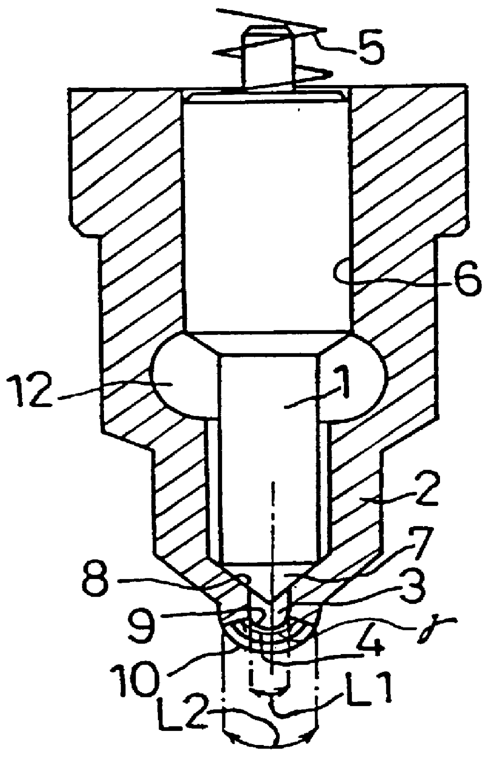
Fuel injection valve and nozzle
a fuel injection valve and nozzle technology, applied in the direction of fuel injecting pumps, machines/engines, mechanical equipment, etc., can solve the problems of fuel injectors that do not note the width and length, fuel injectors used to inject and feed conical fuel, and difficult to compact the combustion chamber 22
- Summary
- Abstract
- Description
- Claims
- Application Information
AI Technical Summary
Benefits of technology
Problems solved by technology
Method used
Image

Examples
first embodiment
[First Embodiment]
In a common plane around the axis of the fuel injector, as shown in FIG. 10, there are formed a plurality of slit-shaped nozzle outlets 14 which have no intersection in their opening directions so that they can spray the fuel dispersedly to inject and feed the fuel over a wide area of the combustion chamber.
second embodiment
[Second Embodiment]
In a common plane around the axis of the fuel injector, as shown in FIG. 11, there are formed a plurality of slit-shaped nozzle outlets 34 which have an intersection in their opening directions so that they can spray the fuel composedly to inject and feed the fuel concentratedly at a local position of the combustion chamber.
third embodiment
[Third Embodiment]
In the axial direction and in a generally common plane of the fuel injector, as shown in FIG. 12, there are formed a plurality of slit-shaped nozzle outlets 44 which are arranged in multiple steps so that they can spray the fuel in layers to inject and feed the fuel over a wide area of the combustion chamber. In this embodiment, the slit-shaped nozzle outlets 44 can be so controlled according to the lift of the needle valve as to inject and feed the fuel from only the lower step, when the lift is small, but from both the upper and lower steps when the lift is large.
PUM
 Abstract
Description
Claims
Application Information