Differential pressure operated free piston for lifting well fluids

a free piston and differential pressure technology, which is applied in the direction of positive displacement liquid engines, wellbore/well accessories, liquid fuel engines, etc., can solve the problems of seal between the plunger and the inner wall of the well conduit, and a large amount of leakage and bypassing between the interior surfaces, so as to eliminate deterioration and replacement problems, the effect of efficient sealing

Inactive Publication Date: 2000-04-04
DINNING ROBERT BENJAMIN
View PDF10 Cites 65 Cited by
  • Summary
  • Abstract
  • Description
  • Claims
  • Application Information

AI Technical Summary

Benefits of technology

In another preferred embodiment of the invention the sealing assembly also comprises a sleeve member which surrounds the intermediate piston body portion and the length of which is less than the length of the elongated cylindrical space in which it is disposed. This allows limited axial movement of the sealing assembly within the cylindrical space between upper and lower terminal positions therein. The piston body is also provided with a central flow passage the lower end of which communicates with a portion of the well conduit below the sealing assembly and the upper end of which is connected to one or more radial passages in the intermediate piston body portion. The radial passages are blocked by the sleeve member in its lower terminal position, blocking fluid flow through the central flow passage. However the sleeve member is provided with one or more radial passages which, when the sleeve member is in its upper terminal positions, are in corresponding registration with the radial passages in the intermediate piston body portion to allow fluid flow through the central flow passage. This position, assumed when the piston is being dropped, allows the piston to gravitate to the bottom of the well in a much shorter time. However, when the piston reaches the piston stop, gravity and inertia cause the sleeve and the elements of the sealing assembly to move to the lower terminal position in which the central flow passage is blocked, allowing gas pressure therebelow to increase for eventually elevating the piston and the well fluids thereabove to the surface.
The differential pressure operated piston of the present invention provides sealing elements which are unique in design. There are two sets, one above the other, of preferably metal pads or cylindrical segments on which are provided cylindrical surfaces for efficient sealing against the inner walls of the well conduit of variable diameter. The juxtaposed sets of pads or segments are radially oriented so that opposing ends thereof seal against each other blocking flow of fluids through the longitudinal separations therebetween. These segments also seal, on the interior thereof, against a rigid ring provided around the intermediate piston body portion, preventing flow of fluids through the space between the intermediate body portion and the segments. Thus no expanding or flexible seal is required beneath the segments or pads, eliminating the deterioration and replacement problems associated with such seals of the prior art. This design allows, as in one embodiment, operation without an internal bypass. In another embodiment, an internal bypass is provided and the sealing assembly is mounted on a sliding sleeve which opens or closes the bypass as desired.
The unique piston assembly designs of the present invention provide reduced leakage, reduced damage from erosion, eliminates the problems associated with a resilient seal and is substantially trouble free in operation. It is easy to assembly, disassemble and use. Many other objects and advantages of the invention will be apparent from reading the description which follows in conjunction with the accompanying drawings.

Problems solved by technology

Most differential pressure operated pistons or plungers of the prior art have inherent problems.
One problem is with the seal between the plunger and the inner walls of the well conduit.
However a considerable amount of leakage and bypassing occurs between the interior surfaces of the pads or segments and the piston body.
In addition, in the piston designs of the prior art, the segments or pads inherently leak through the longitudinal spaces or separations between adjacent segments or pads.
This type of leakage also increases the pressure necessary for lifting of the piston and well fluids, requiring more piston trips.
Furthermore, the flow and leakage between the interior of the segments or pads and the piston body and between the spaces between the longitudinal separation or spaces between segments or pads causes erosion which will erode the piston body and the sealing elements, further increasing the pressure necessary to elevate the piston and well fluids to the surface of the well and eventually eroding these elements to such an extent that they are no longer useable, requiring repair and or replacement at considerable expense.
Such a design severely restricts flow through the internal flow passage as the plunger is falling back to the bottom of the well.
This type of design is costly, requires corrections for the additional moving weight and creates other hazards for the piston as it returns to the surface.
If not, the piston will fall erraticly and may not reach the depth required to close its valve.
If the valve does not close the piston will not return to the surface on its own accord, requiring a costly fishing operation to free the piston.
In addition to the above mentioned problems, the rod provided to the valve is necessarily small, fragile and susceptible to damage.
This requires accurate and sensitive adjustments which are not always possible in field situations.
Furthermore, there are many hazards and damage possibilities when the piston, traveling under pressure, is propelled against a stationary rod.
There are so many disadvantages of this design, that very few well operators utilize it.
While this tool is much more effective than those of the prior art, the overlapping or stepped cylindrical segments are not easily manufactured.

Method used


Image

  • Differential pressure operated free piston for lifting well fluids
  • Differential pressure operated free piston for lifting well fluids
  • Differential pressure operated free piston for lifting well fluids

Examples


Embodiment Construction

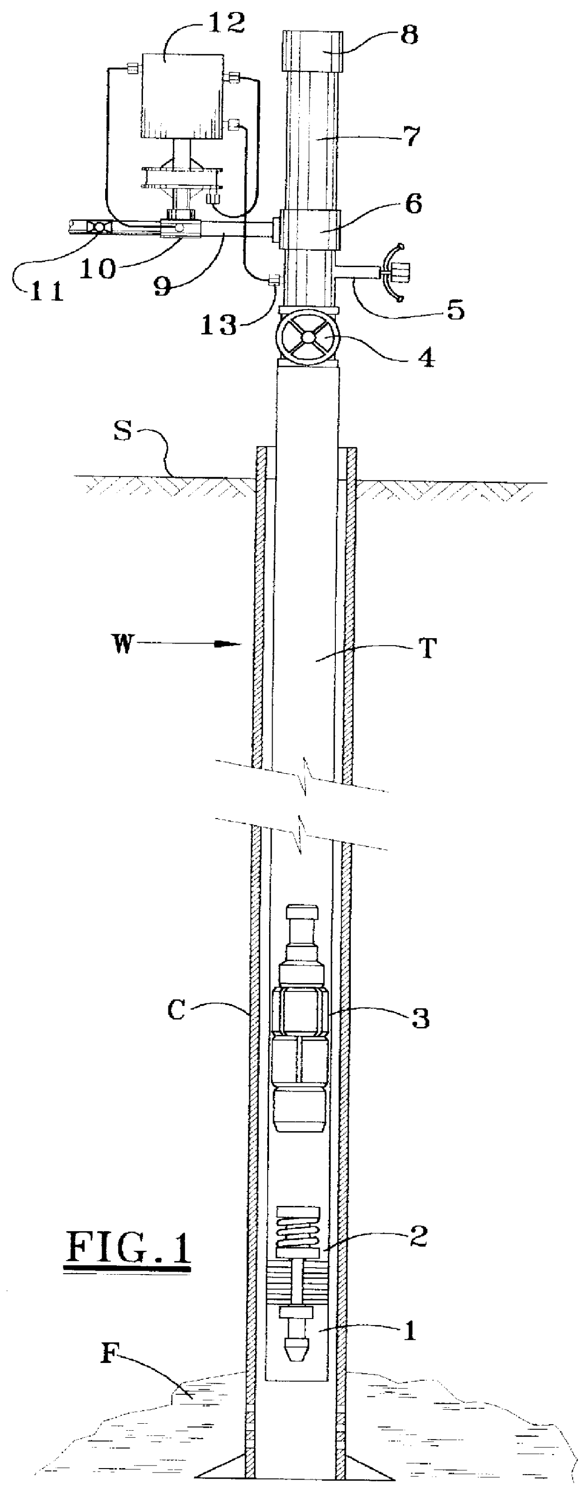
Referring first to FIG. 1 there is shown a well W for producing hydrocarbon fluids from a subterranean formation F. One or more well conduits extend from the subterranean formation F to the surface. In the exemplary embodiment there is a casing string C, and concentrically therein, a tubing string T. The tubing string T, which may be referred to as the production string, may sometimes exist without a casing string. In any event, the tubing string T is the well conduit through which fluids from the subterranean formation F flow or are raised to the surface S.

Near the bottom of the tubing string T is a retrievable and standing valve assembly 1 and a stop mechanism 2 mounted in any conventional manner, e.g. slips. These elements may be relocated by wire line operations or the like from the surface of the well W, at different depths, as well conditions change. The stop mechanism 2 would preferably incorporate a spring of some type for arresting downward movement of a free piston type pu...


PUM


Abstract

A differential pressure operated free piston for lifting well fluids from a subterranean reservoir to the surface through a well conduit. The free piston includes a piston body adapted for up and down sliding disposition within the conduit and a sealing assembly carried in a cylindrical space surrounding the piston body. The sealing assembly includes upper and lower juxtaposed sets of longitudinally separated cylindrical segments providing relatively smooth cylindrical surfaces on the exterior thereof for sliding and sealing contact with inner walls of the conduit, the upper and lower set of segments being radially oriented so that separations between the segments of the upper set and separations between the segments of the lower set are not aligned, providing a seal which, when pressure in the well conduit near the surface is subsequently reduced, sufficiently elevates the piston and well fluids thereabove to the surface.

Description

1. Field of the InventionThe present invention pertains to apparatus for lifting well fluids from a subterranean reservoir. More specifically, the present invention pertains to differential pressure operated free pistons, sometimes referred to as "gas operated plungers", for lifting well fluids from a subterranean reservoir through a well conduit which extends to the surface.2. Description of the Prior ArtDifferential pressure operated pistons, or plungers, have long been utilized in producing subterranean wells where the natural gas pressure in the well is insufficient to produce a free flow of fluids to the surface. Such devices generally include a free piston or plunger element which slidingly and sealingly engages the inner walls of a well conduit which extends upwardly from the well reservoir to the surface. The well conduit, normally referred to as a production string, may be either a casing string or a tubing string disposed within a casing string.Typically, the free piston o...

Claims


Application Information

Patent Timeline
Patent Type & Authority Patents(United States)
IPC IPC(8): E21B43/12F04B47/12F04B53/00F04B53/14F04B47/00
CPCE21B43/121F04B53/143F04B47/12
Inventor DINNING, ROBERT W.
Owner DINNING ROBERT BENJAMIN
Why Eureka
Try Eureka