Continuous, linearly intermixed fiber tows and composite molded article thereform

Inactive Publication Date: 2000-04-04
CYTEC TECH CORP
View PDF28 Cites 44 Cited by
  • Summary
  • Abstract
  • Description
  • Claims
  • Application Information

AI Technical Summary

Benefits of technology

The fiber blends prepared according to the instant invention are flexible and handleable and have good draping properties, so that they can be used to form intricately shaped articles. In addition, because of the intermixing of the two fibers, good wetting of the carbon fiber by the thermoplastic material is obtained when appropriate heat and pressure are applied to the mold. Good wetting is obtained in large measure because of the substantially uniform distribution of the thermoplastic fiber an

Problems solved by technology

For example, using the prior art tapes, it was not possible in many instances to prepare ar

Method used


Image

  • Continuous, linearly intermixed fiber tows and composite molded article thereform
  • Continuous, linearly intermixed fiber tows and composite molded article thereform
  • Continuous, linearly intermixed fiber tows and composite molded article thereform

Examples


example 1

A liquid crystal polymeric (LCP) fiber tow based upon a copolymer prepared from 6-hydroxy-2-napthoic acid and p-hydroxy benzoic acid was obtained. The LCP had a density of 1.4 g / cc, and the tow itself was formed of 660 filaments (2.25 denier per filament). The tow had an initial modulus of 5670 gms, a tenacity of 10.5 g / denier, and an elongation of 2%. The second fiber to be used for intermixing with the LCP fiber was Celion 3000 carbon fiber (3000 filament count), having a density of 1.7 g / cc, a tensile strengh of 515.times.10.sup.3 psi, a tensile modulus of 34.times.10.sup.6 psi and an ultimate elongation of 1.5%. The carbon fiber is produced from a polyacrylonitrile precursor and is available from Celanese Specialty Operations, Hercules and Union Carbide.

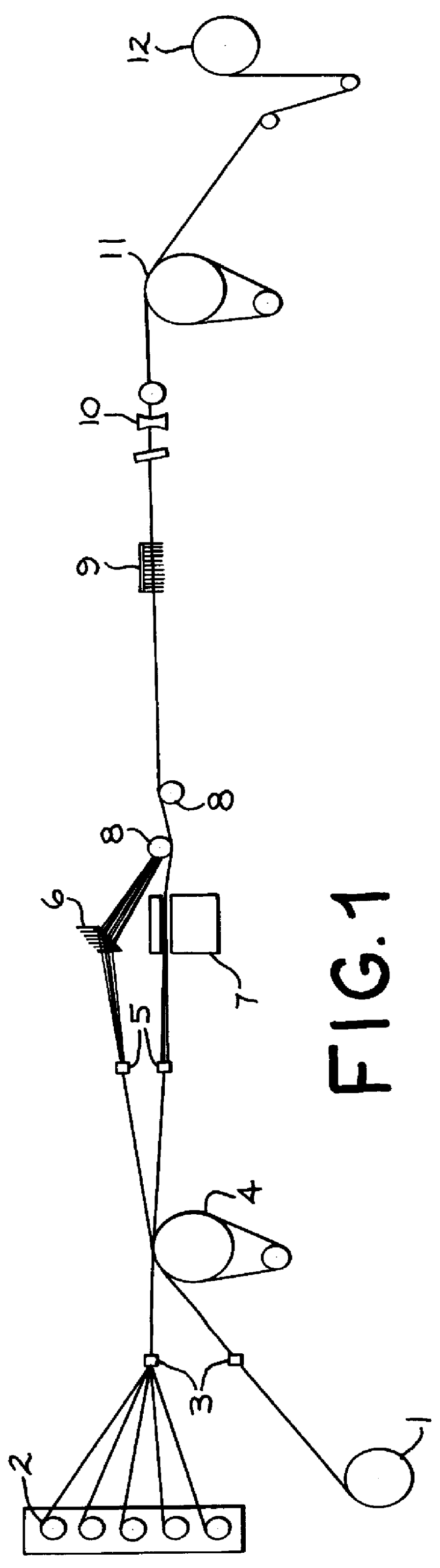
Bobbins containing the LCP polymeric fiber tow and the Celion fiber tow were spaced apart on a bobbin rack. Fibers from both bobbins were fed onto and separately wrapped around a Godet roll, so that upon mixing the mixed tow woul...

example 2

Utilizing the same carbon fiber as described in Example 1, an approximate 50% by volume polybutylene terephthalate (PBT) / carbon fiber blend was prepared. The polybutylene terephthalate material had a density of 1.34 g / cc and a denier of 1520 g / 9000 m. The polybutylene terephthalate had a draw ratio of 2.25-1, an initial modulus of 24 g, a tenacity of 5.3 g / denier, an elongation of 28%, a melting point of 227.degree. C. and a denier per filament of 2.7. Seventeen packages of 33 filament count yarn were employed on a creel, and all packages were merged into a single polybutylene terephthalate fiber tow on a Godet roll. Maintained separately, but on the same Godet roll, was one package of 3000 filament count carbon fiber to provide a total approximate blend of 50 / 50 by volume carbon fiber / PBT.

The polybutylene terephthalate tow was fed through a fiber comb having approximately 30 teeth, while the carbon fiber tow was fed through a gas banding jet operating as described in Example 1, at ...

example 3

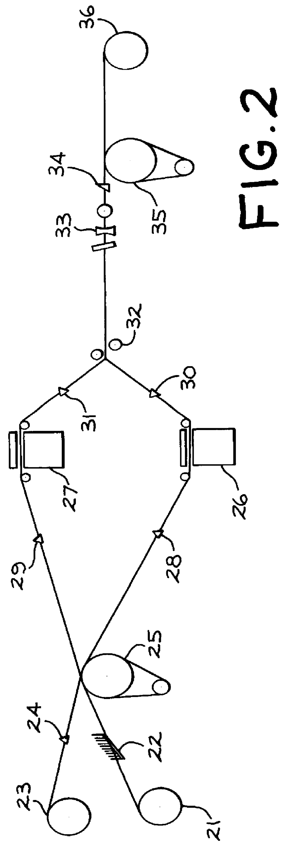
An approximate 50 / 50% by volume blend was prepared based upon the carbon fiber described in Example 1 and a polyether ether ketone (PEEK) thermoplastic polymer. The fiber prepared from the PEEK had a density of 1.3 g / cc, a melting point of 338.degree. C., an initial modulus of 53 grams, a tenacity of 2.7 g / denier, an elongation of 63%, and in 10 filaments per package tows a dpf of 367 (g / 9000 m). Four (10 filaments per package) tows were placed on a creel and the fibers were blended together on a Godet roll, but maintained separately from the carbon fiber which was also wrapped around the Godet roll. The PEEK fiber was then directed through a fiber comb as described in Example 2 and into a gas banding jet. The carbon fiber after leaving the Godet roll also entered a gas banding jet. Both jets were operating at a pressure of about 3 psi. After leaving the jets the fibers were intermixed above and below two parallel, longitudinally extended rods and fed through a second parallel fiber...


PUM

PropertyMeasurementUnit
Angleaaaaaaaaaa
Percent by massaaaaaaaaaa

Abstract

The instant invention involves a process used in preparing fibrous tows which may be formed into polymeric plastic composites. The process involves the steps of (a) forming a carbon fiber tow; (b) forming a thermoplastic polymeric fiber tow; (c) intermixing the two tows; and (d) withdrawing the intermixed tow for further use.

Description

BACKGROUND OF INVENTIONThis invention relates to processes for preparing fibers useful in forming composite articles. More particularly, this invention relates to carbon fiber-containing fiber blends which are useful in preparing composite articles.Carbon fiber-containing tapes and rovings have been known for several years. See, for example, U.S. Pat. Nos. 3,704,485, 3,873,389, and 3,795,944, as well as U.S. Pat. Nos. 3,993,726 and 3,728,424.Also it is known to intermix two similar or different types of fibers, particularly to obtain high bulk. See for example, U.S. Pat. Nos. 4,219,997, 4,218,869, 3,959,962, 3,968,638 and 3,958,310. And the combining of different types of fibers has been facilitated using various types of fluid jets. See, e.g., the '310 patent and U.S. Pat. No. 4,147,020. However, in the '020 patent, after combining the yarns are cut into short lengths.U.S. Pat. No. 4,226,079, issued Oct. 7, 1980, discloses the combining of two different types of fibers, in order to...

Claims


Application Information

Patent Timeline
IPC IPC(8): B29C70/04B29C70/50A63B51/02B29B15/10B29C70/20D02G3/40
CPCB29C70/50D02G3/402A63B51/02B29C70/20B29B15/12Y10T428/2929B29K2105/101B29K2301/12B29K2307/00B29L2031/5245Y10T428/2918Y10T428/2913Y10T428/2931Y10T428/2916B29K2105/0079Y10T442/313Y10T428/249942Y10T428/24994Y10T442/2361Y10T428/249945
Inventor MCMAHON, PAUL E.CHUNG, TAI-SHUNGYING, LINCOLN
Owner CYTEC TECH CORP
Why Eureka
Try Eureka