Instrument for measuring leakage power leaking to adjacent channel

Inactive Publication Date: 2000-04-04
ANRITSU CORP
View PDF8 Cites 10 Cited by
  • Summary
  • Abstract
  • Description
  • Claims
  • Application Information

AI Technical Summary

Benefits of technology

Accordingly the object of the present invention is to provide an adjacent and alternate channels power measurement apparatus which can accurately detects the specific region of

Problems solved by technology

If the frequency range for the components of the modulated signal broadens, the component of communication signal a to be transmitted on the carrier will acts as leakage power, adversely influencing adjacent communication signal lines on adjacent carriers.
As shown in FIG. 7A, however, it is difficult to detect the rising position and falling position of the burst signal received in the narrow band.
With the position-determining metho

Method used


Image

  • Instrument for measuring leakage power leaking to adjacent channel
  • Instrument for measuring leakage power leaking to adjacent channel
  • Instrument for measuring leakage power leaking to adjacent channel

Examples


Example

First Embodiment

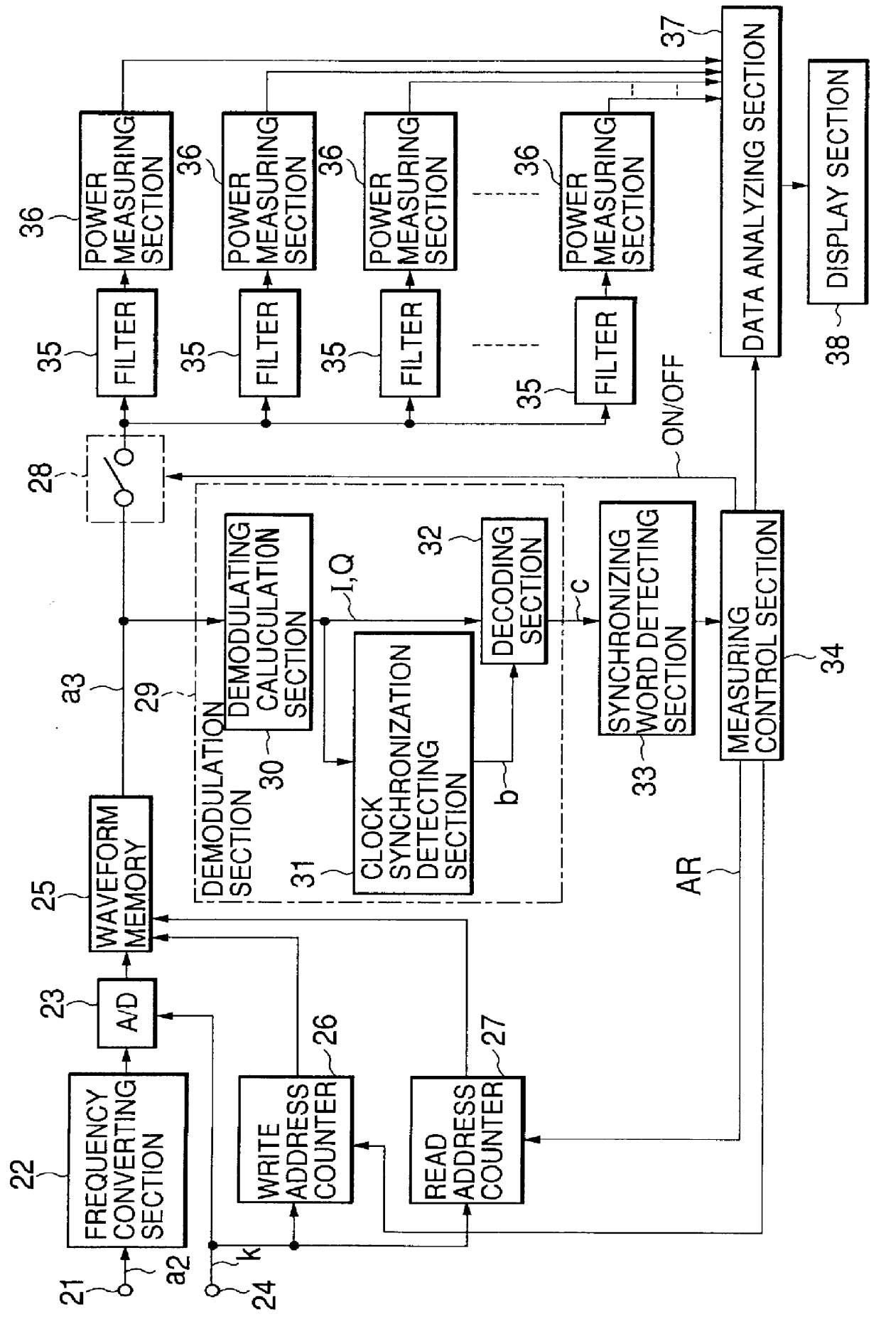
FIG. 1A is a block diagram schematically showing the adjacent and alternate channels power measurement apparatus according to the first embodiment of the invention.

An input signal a.sub.2 composed of a burst signal input to an input terminal 1 and having the waveform shown in FIG. 2 is supplied to a frequency converting section 22.

The input signal a.sub.2 has been generated by modulating a carrier having a carrier frequency f.sub.c, with the digital data which is to be transmitted.

As shown in a transmission frame formed in a signal region T.sub.1, the input signal a.sub.2 has ramp time R at the heat. It further has a start symbol SS, a preamble PR, a synchronizing word UW, a channel type C1, SACCH (SA), data channel TC in which the data to be transmitted is set, a cursing symbol CRC, and a guard time, all arranged sequentially after the ramp time R.

The carrier frequency of the input signal a.sub.2, for example, 890.2 Mhz, is converted by frequency converting section ...

Example

Second Embodiment

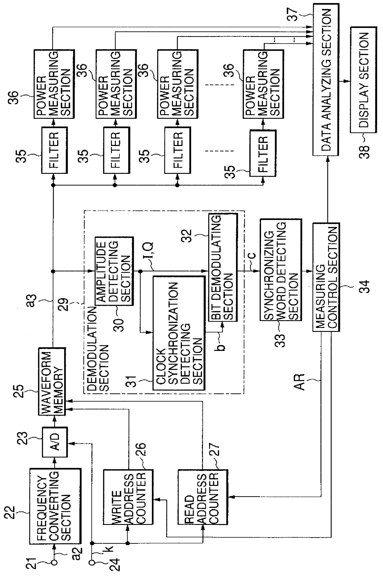
FIG. 4A is a block diagram schematically showing the adjacent and alternate channels power measurement apparatus according to the second embodiment of the invention.

The components identical to those of the first embodiment, i.e., the adjacent and alternate channels power measurement apparatus shown in FIG. 1A, are designated at the same reference numerals in FIG. 4A, and will not be described in detail.

The measuring apparatus according to the second embodiment incorporates one digital filter 35a and one power measuring section 36a, not a plurality of filters 35 and a plurality of power measuring sections 36 as in the first embodiment.

The pass-frequency band BW of the digital filter 35a can be changed in accordance with an instruction supplied from the measuring control section 34a.

To be more specific, the measuring control section 34a sequentially sets pass-frequency bands BW1, BW.sub.2, BW.sub.3, BW.sub.4, . . . in the digital filter 35a, for a plurality of channel...


PUM


Abstract

PCT No. PCT/JP97/01878 Sec. 371 Date Mar. 4, 1998 Sec. 102(e) Date Mar. 4, 1998 PCT Filed Jun. 3, 1997 PCT Pub. No. WO98/01965 PCT Pub. Date Jan. 15, 1998In order to measure the leakage power of a communications signal using a burst signal, with respect to adjacent channels, an input signal containing a modulated signal is subjected to A/D conversion in an A/D converter 23 and then written into a waveform memory 25. The input signal read from the waveform memory is demodulated to digital data by means of a demodulating section 29. An extraction region calculating section 33 detects the position of a synchronizing word in the digital data demodulated, and determines the extraction region AR of the input signal stored in the waveform memory 25. One filter 35a or a plurality of filters 35 allow passage of the signal components in the frequency bands of the channels adjacent to the main channel. Switching sections 34 and 28 supply the signals in the extraction region determined, which are included in the input signal stored in the waveform memory 25. One power measuring section 35a or a plurality of power measuring sections 35 measure the power of each signal component which has passed through one filter.

Description

The present invention relates to an adjacent and alternate channels power measurement apparatus which measures leakage power in the adjacent and alternate channels in TDMA (Time Division Multiple Access) communication, wherein transmission is modulated by digital data which is set in a transmission frame containing a synchronizing word.Mobile communications systems such as mobile telephones and portable telephones adopt TDAM (Time Division Multiple Access) system, so that they may efficiently use communications lines as communications systems between a base station and radio devices which operate as mobile terminals.Some specific examples of the mobile communications systems adopting the TDMA system are PDC (Personal Digital Cellular System; Japan), PHS (Personal Handyphone System; Japan), and GSM (Global System for Mobile Communications; Europe).In these systems, communication signals or burst signals are exchanged between the base station and each radio device (i.e., a mobile stat...

Claims


Application Information

Patent Timeline
IPC IPC(8): H04B17/00H04B7/005H04B17/354H04W24/00H04W88/02
CPCH04W52/04H04B17/16H04B17/102H04W52/16
Inventor TAGAWA, CHIHIRO
Owner ANRITSU CORP
Why Eureka
Try Eureka