Method of grinding the teeth of spiral-toothed bevel gear wheels

a technology of spiral-toothed bevel gear wheels and grinding methods, which is applied in the direction of gear teeth, mechanical equipment, manufacturing tools, etc., can solve the problems of only being able to produce bevel gears with circular arc gear teeth, not being able to selectively realize differences in intermittent indexing processes,

Inactive Publication Date: 2000-04-18
KLINGELNBERG AG
View PDF11 Cites 30 Cited by
  • Summary
  • Abstract
  • Description
  • Claims
  • Application Information

AI Technical Summary

Problems solved by technology

In contrast thereto it is not possible in connection with the intermittent indexing processes to selectively realize the difference, which essentially relates to the production of the pitch, during production.
While for commercial reasons the continuous indexing method is preferred for the involute and cycloid teeth, the production of bevel gears with circular arc gear teeth is only possible by means of the intermittent indexing process.
However, both the Gleason and the Klingelnberg methods cause a limitation to a particular wheel body geometry with conically extending tooth depth, i.e. the tooth depth increases from the inside to the outside in the linear tooth direction.
Unfortunately, however, the particular advantage of grinding with the dual grinding head, namely that it is possible by means of two grinding disks to optimize both flanks independently of each other, is lost.
If, with the completing method, one flank is optimized, the other flank is unavoidably also affected, so that flank optimization becomes difficult.

Method used


Image

  • Method of grinding the teeth of spiral-toothed bevel gear wheels
  • Method of grinding the teeth of spiral-toothed bevel gear wheels
  • Method of grinding the teeth of spiral-toothed bevel gear wheels

Examples


Embodiment Construction

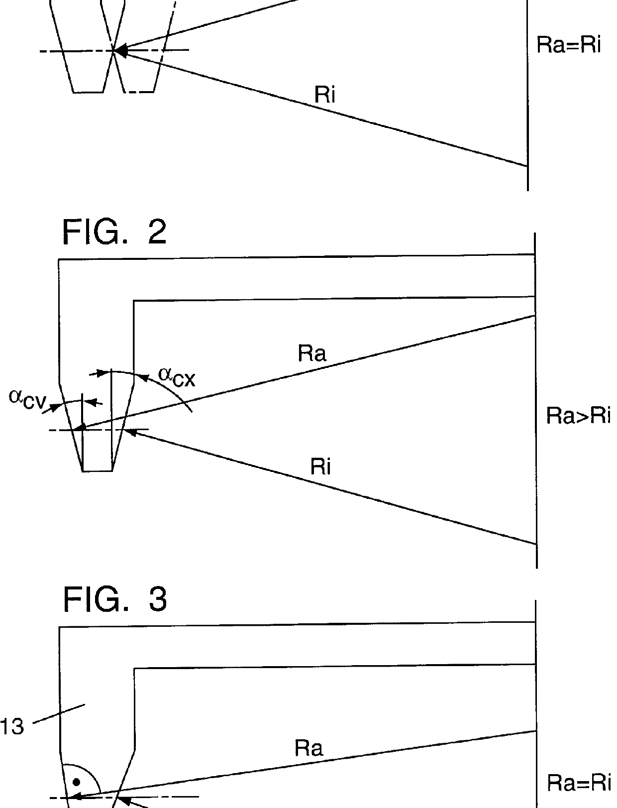
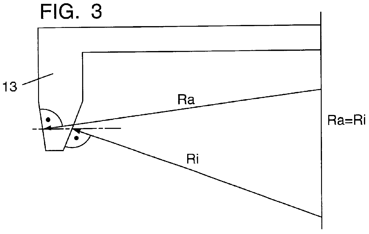
As already mentioned above, FIG. 3 shows a grinding disk known from the so-called completing method, wherein the generating angles of the grinding disks have been changed in that the angle .alpha..sub.cv of the outer cone (in respect to the representation in FIG. 2) has been decreased, and the angle .alpha..sub.cx of the inner cone (again in respect to the representation in FIG. 2) has been increased, so that

Ra=Ri

applies. In the manner explained above and represented in FIGS. 4 and 5, the convex flank of the helical teeth of a ring gear 14 is worked in one cycle by means of the grinding disk 13 during upward generating (FIG. 4), and the concave flank in another cycle during downward generating (FIG. 5). In the reversing points between downward and upward generating, the machine setting is then changed in such a way that the correct pressure angle and the correct flank topography are created by simulation of an angle of inclination (TILT) of the grinding disk or by an additional move...


PUM

PropertyMeasurementUnit
machine base angleaaaaaaaaaa
flank anglesaaaaaaaaaa
pressure angleaaaaaaaaaa

Abstract

PCT No. PCT / EP96 / 02020 Sec. 371 Date Nov. 5, 1997 Sec. 102(e) Date Nov. 5, 1997 PCT Filed May 10, 1997 PCT Pub. No. WO96 / 35541 PCT Pub. Date Nov. 14, 1996Disclosed is a method of grinding bevel gear teeth in an intermittent indexing process using a single grinding wheel provided with different bevel angles ( alpha ) to produce the desired grinding wheel radii (R): one flank is machined during grinding in downward generation as far as a first turning point, another flank is produced in upward generation as far as a second turning point, and machine settings are so adjusted in the turning points as to ensure a correct pressure angle and correct flank topography during the generating process, irrespective of the different bevel angles ( alpha ). The process combines the advantages of the known completing process, by which both flanks can be ground at the same time at the cost of imposing a particular wheel body geometry with conical teeth, with those of the known two-track process for grinding both flanks with a double grinding head, by which various additional correction factors can be introduced to optimize the flank shape for convex and concave flanks.

Description

DESCRIPTION1. Technical FieldThe invention relates to a method of the type recited in the preamble of the claim.2. Background ArtThere are bevel gear teeth which are produced in a continuous indexing process and those which are produced with the two-axis method or intermittent indexing process. Since the demands on the gears in respect to load-bearing capacity, accuracy and quiet running have continuously increased in the past years, special production methods have been created which, in contrast to lapping after hardening, provide fine machining. There are essentially three basic forms of spiral-toothed bevel gears based on the differences in respect of the longitudinal line of tooth:a circular arc constituting the longitudinal tooth line,an involute constituting the longitudinal tooth line,an extended epicycloid constituting the longitudinal tooth line.The manufacture of bevel gears with a circular arc as the longitudinal tooth line takes place by means of the intermittent indexin...

Claims


Application Information

Patent Timeline
Patent Type & Authority Patents(United States)
IPC IPC(8): B23F9/00B23F9/02
CPCB23F9/025
Inventor WIENER, DIETER
Owner KLINGELNBERG AG
Why Eureka
Try Eureka