Antenna system for millimeter wave length communication systems

a communication system and millimeter wave technology, applied in the direction of antennas, radiating element structural forms, de-icing/drying arrangements, etc., can solve the problems of increasing the capital and operating costs of these planar array antennas, and achieve the effect of accurate aiming

Inactive Publication Date: 2000-04-18
KHARADLY MOSTAFA Z +1
View PDF5 Cites 4 Cited by
  • Summary
  • Abstract
  • Description
  • Claims
  • Application Information

AI Technical Summary

Benefits of technology

The angle .alpha. of the radiating surface of the antenna to the horizontal is set based on the optimum to protect the radiating surface from rain while still permitting the beam to be accurately aimed at the satellite or target 18 without impairing significantly the power of the main beam 16. The radiating angle .theta. of the main beam 16 to the radiating face 12 is then set equal to the difference between the elevation angle c and the angle .alpha. of the radiating face 12 to the horizontal to thereby aim or focus of the main beam 16 toward the satellite or the like 18.
If desired, a suitable umbrella like structure as indicated at 20 may be made to project beyond the free end 22 of the antenna 10 to help shield the radiating face 12 from rain. Also, if desired, a barrier 24 may be positioned spaced from the radiating face 12 in a position to further protect the radiating surface 12 from rain without interfering with the trajectory of the main beam 16 from the antenna 10 to the target 18.
It is also possible to wrap the antenna in a suitable plastic wrapping (not shown) to help to prevent water from penetrating the antenna structure.

Problems solved by technology

Water or condensate present on the radiating face of planar array antenna interferes with reception or transmission of these short waves and thereby necessitates the use of much more sophisticated electronics to obtain a meaningful signal from the distorted signal available from the wet antenna.
This wetting phenomenon significantly increases the capital and operating cost of these planar array antennas.

Method used


Image

  • Antenna system for millimeter wave length communication systems
  • Antenna system for millimeter wave length communication systems
  • Antenna system for millimeter wave length communication systems

Examples


Embodiment Construction

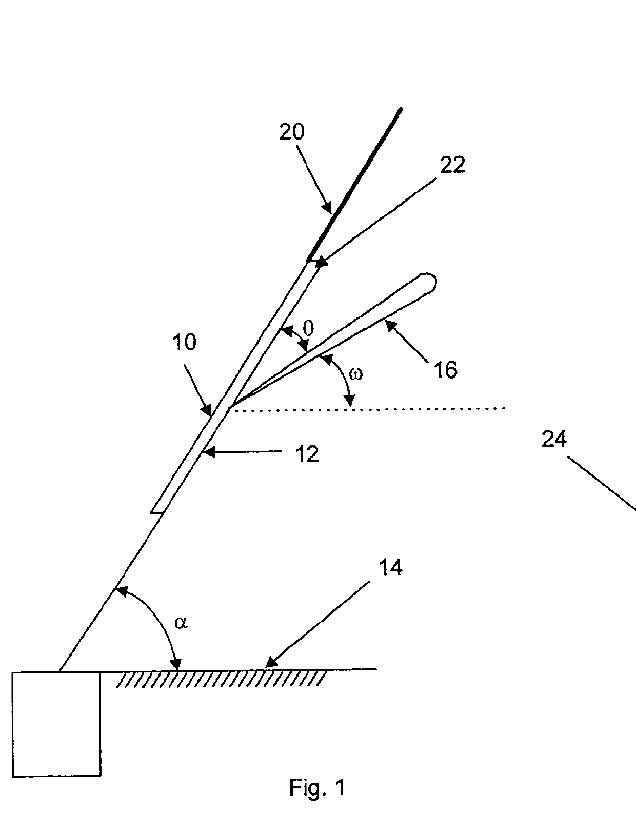
An antenna was set up as a receiving antenna with its main beam angle .theta. set at 32.degree. to the plane of the radiating apertures. The antenna was wrapped in a thin plastic sheet to prevent moisture from entering the antenna system.

A continuous wave source with a centre frequency of operation was 39.5 GHz provided incident radiation at 32.degree. to the horizontal on the antenna at a power level that was randomly variable with time within .+-.1 dB.

The antenna was tested in two different mounting configurations

a) Horizontal--with the radiation apertures facing upward, and

b) Inverted--with the radiating face at an angle .alpha. to the horizontal of 64.degree. and facing downwards.

It will be apparent that in both cases a) and b) the look or elevation angle .omega. was the same i.e. 32.degree. or 64-32=32.degree..

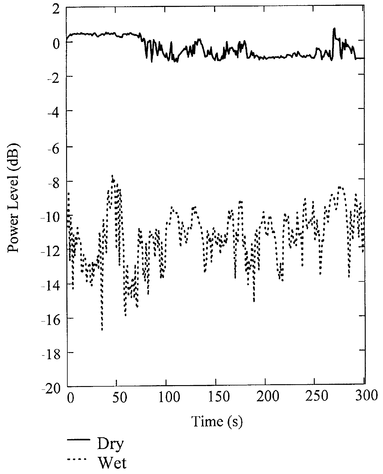
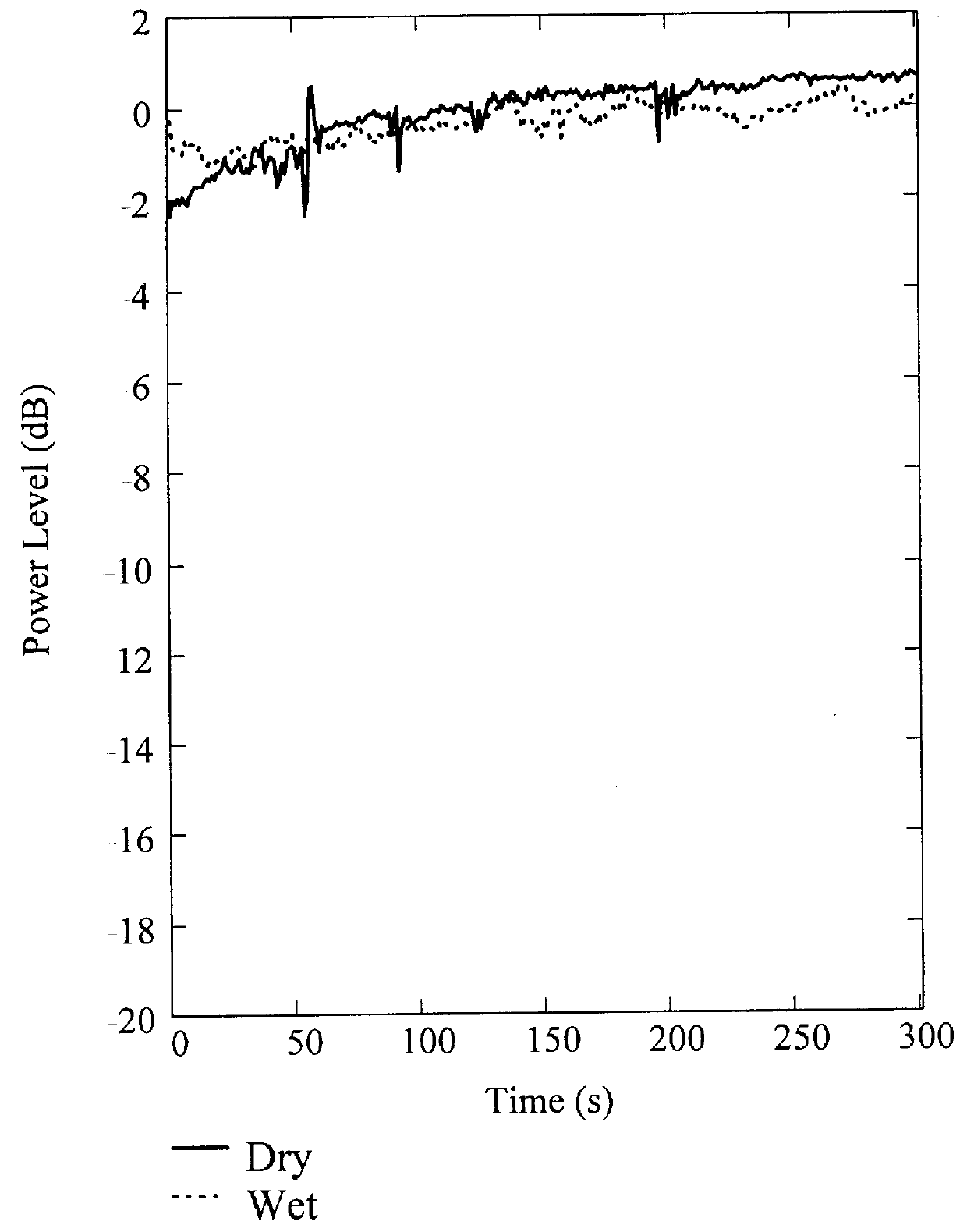
Water was rained down on the antenna from 4 shower heads to simulate rain. The shower permitted varying the intensity and drop size of the simulated rain.

The received pow...


PUM


Abstract

The effect of rain wetting a planar array antenna is reduced substantially by mounting the antenna with its radiating face facing downwards on an angle alpha of about 30-80 DEG to the horizontal and adjusting the angle theta of the main beam of the planar array antenna to its radiating face so that the angle theta of the main beam to the radiating face of the antenna and the angle alpha of the radiating face to the horizontal combine to direct the main beam at the elevation angle omega toward a selected target.

Description

The present invention relates to antennas, more particularly the present invention relates to a system for minimizing the effect of rain wetting the radiating surface of a planar array antenna.The term "planar array antenna" used in this application is intended to include resonant and non-resonant slotted arrays excited by a wave guide or micro-strip network and Micro-strip antennas normally formed by micro-strip patches, stubs or dipoles etched in the surface of a metal cladded dielectric substrate. Micro-strip antennas are usually fed via a micro-strip but wave guides or coaxial feeds may also be used. The term "planar array antenna" further includes dielectric resonant antennas excited either by a micro-strip or wave guide network.The problem of rain wetting antenna particularly planar array antennas used for short wave length transmissions, i.e. transmissions with wavelengths in the millimeter range are well recognized. Water or condensate present on the radiating face of planar...

Claims


Application Information

Patent Timeline
Patent Type & Authority Patents(United States)
IPC IPC(8): H01Q1/02H01Q21/06H01Q1/42
CPCH01Q1/02H01Q21/061H01Q1/42
Inventor KHARADLY, MOSTAFA Z.CHAN, AMIEE Y.
Owner KHARADLY MOSTAFA Z
Why Eureka
Try Eureka