

Embossing and laminating machine with embossing cylinders having different rotational speed
a technology of embossing cylinders and laminating machines, which is applied in the direction of manufacturing tools, soldering devices, auxiliary welding devices, etc., can solve the problems of serious problems, loss of adhesion between the embossing machine and the adjustment of the embossing machine, and long and complex operation
- Summary
- Abstract
- Description
- Claims
- Application Information
AI Technical Summary
Benefits of technology
Problems solved by technology
Method used
Image

Examples
Embodiment Construction
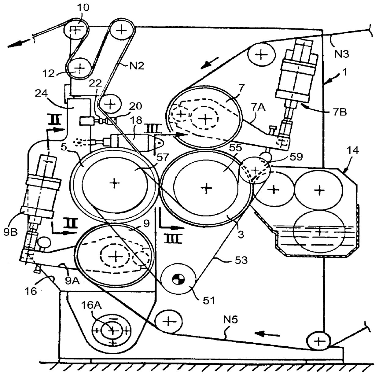
With reference to FIG. 1, an embossing and laminating machine, indicated by the number 1, will be described initially in a summary way.
Two embossing cylinders 3 and 5, disposed with parallel axes, and having their surfaces provided with protuberances for embossing, are mounted on the frame of the machine 1. In the nip formed by the two cylinders 3 and 5, the protuberances (or rather some of them, as will be explained subsequently) are in contact with each other.
The embossing cylinder 3 interacts with a pressure roller 7 which may also be provided with an embossed surface, or may be covered with a yielding material such as rubber or the like. The number 9 indicates a second pressure roller similar to the roller 7 and interacting with the embossing cylinder 5. The two pressure rollers 7 and 9 are mounted on corresponding moving elements 7A and 9A which are hinged and subject to an elastic force, for example through two cylinder and piston systems 7B, 9B which press the corresponding p...
PUM
| Property | Measurement | Unit |
|---|---|---|
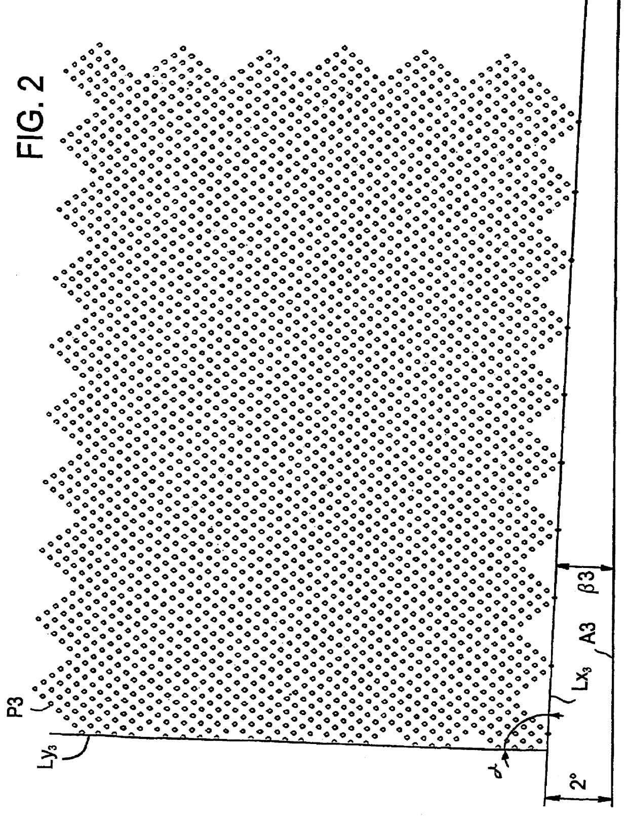
| angle β3 | aaaaa | aaaaa |
| angle | aaaaa | aaaaa |
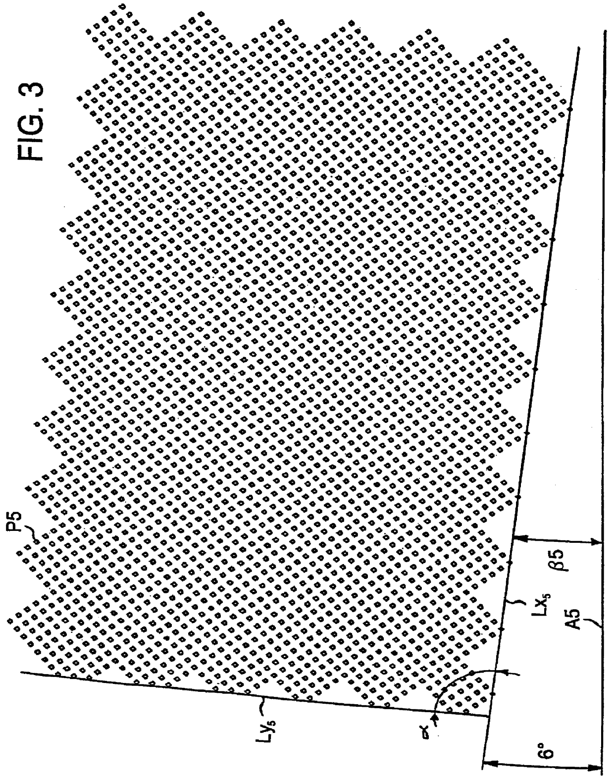
| angle β5 | aaaaa | aaaaa |
Abstract
Description
Claims
Application Information