Method for reducing shorts on a printed circuit board edge connector

a technology of printed circuit board and edge connector, which is applied in the manufacture of contact parts, coupling device connections, conductive pattern reinforcement, etc., can solve problems such as tab "short circuit", undesirable electrical connections, and the approach does not always prevent shorts

Inactive Publication Date: 2000-05-02
IBM CORP
View PDF1 Cites 7 Cited by
  • Summary
  • Abstract
  • Description
  • Claims
  • Application Information

AI Technical Summary

Problems solved by technology

Because of the dense spacing between tabs, however, when the board is inserted into the connector, it is quite common for a tab to "short circuit" by mating with the wrong connector contact.
This causes an undesirable electrical connection.
While the use of a card guide helps

Method used


Image

  • Method for reducing shorts on a printed circuit board edge connector
  • Method for reducing shorts on a printed circuit board edge connector
  • Method for reducing shorts on a printed circuit board edge connector

Examples


Embodiment Construction

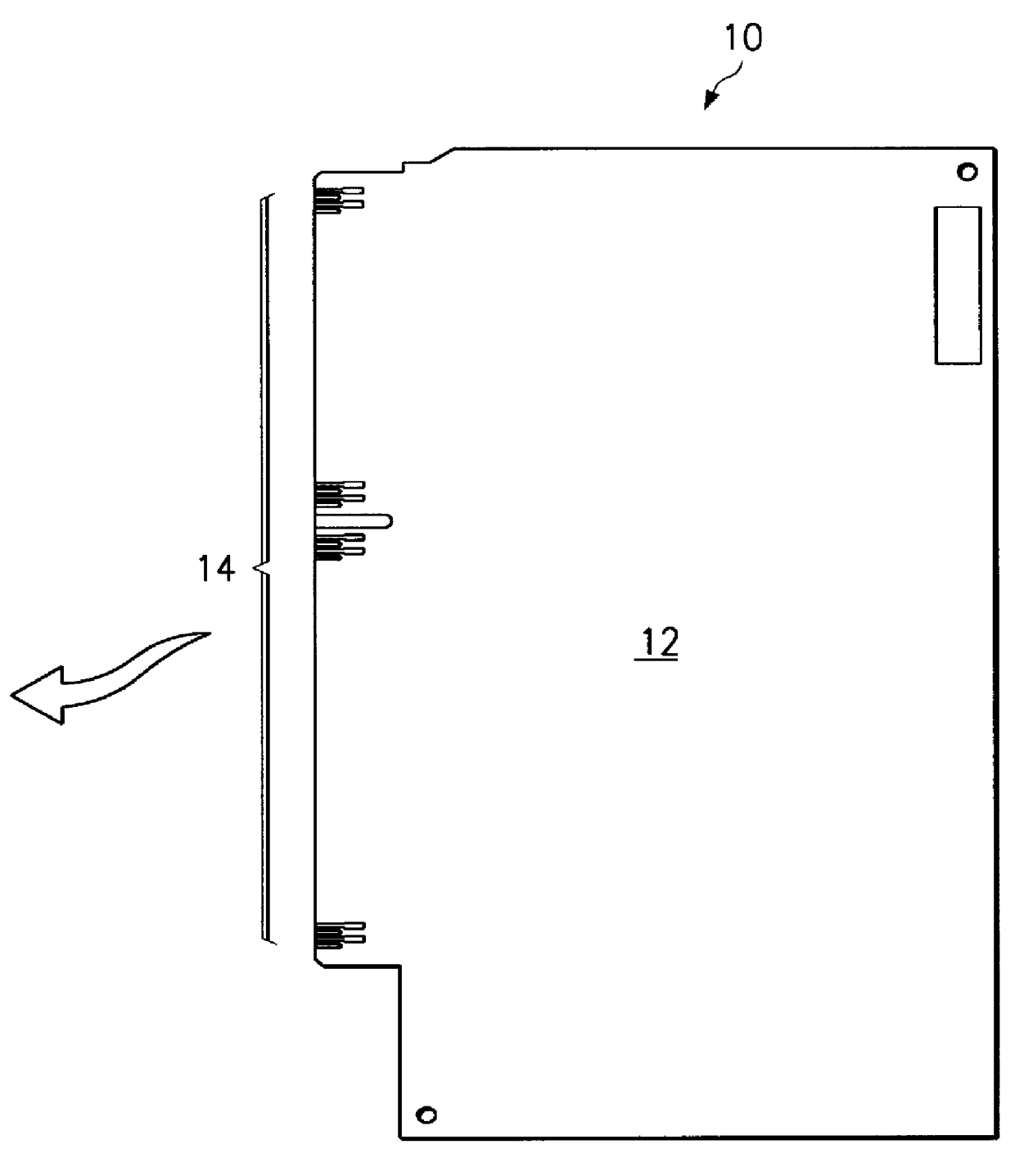
The present invention is implemented in any apparatus in which a printed circuit board having electrical contacts is plugged into a connector socket. By way of example only, one such apparatus is a computer, for example, an IBM RS / 6000 computer (a reduced instruction set of so-called RISC-based workstation) running the AIX (Advanced Interactive Executive Version 4.1 and above), or an Intel-based processor system running the Windows NT or OS / 2.RTM. operating system. Other applications of the present invention include printed circuit boards or other "cards" used in communications equipment, audio equipment and games, among other types of electrical devices. Indeed, any application that requires a connector with many electrical signals in a small connection area may take advantage of the present invention. For illustrative purposes, however, the remainder of the Detailed Description relates to a pluggable component card for use in a computer.

One such card 10 is illustrated in FIG. 1. I...


PUM

PropertyMeasurementUnit
Electrical conductoraaaaaaaaaa
Metallic bondaaaaaaaaaa
Surface areaaaaaaaaaaa

Abstract

An edge connector for a circuit board having a top layer and at least one layer underlying the top layer to form a composite structure. The edge connector comprises a first set of metallic tabs formed on the top layer in a row spaced from an edge of the top layer, with each of the first set of metallic tabs having a plating spoke associated therewith formed in the one layer underlying the top layer. A second set of metallic tabs is formed on the top layer in a row adjacent the edge. A metallic tab of the first set is positioned between a pair of metallic tabs in the second set, however, the surface area of the top layer between each pair of metallic tabs in the second set is substantially free of a plating spoke.

Description

1. Technical FieldThe present invention generally relates to techniques for improving the alignment between electrical contacts on a printed circuit board and an associated socket connector to thereby reduce shorts when the board is plugged into the socket.2. Description of the Related ArtA typical computer is highly modular. During a computer's useful life, one or more components are replaced either due to maintenance or system upgrades. To this end, most computer components are now designed to be "field replaceable" and are supported on a "pluggable" printed circuit board. The board typically includes a so-called "edge connector" having metallic "tabs" that mate with spring contacts located within a connector socket, which in turn is supported on a motherboard. Each tab should mate with a specific spring contact when the printed circuit board is inserted into the connector socket. Because of the dense spacing between tabs, however, when the board is inserted into the connector, it...

Claims


Application Information

Patent Timeline
IPC IPC(8): H05K1/11H05K3/24H01R43/16H05K3/00H05K3/46H01R12/72
CPCH05K1/117H05K3/242H01R12/721H01R43/16H05K3/0052H05K3/4623H05K2201/0919Y10T29/49213H05K2201/09709Y10T29/49222Y10T29/49204Y10T29/49208H05K2201/09481
Inventor BERTO, DANIEL JAMESCOE, JIMMY MELVINLAWRENCE, JR., LLOYD ARCHIBALD BARRINGTONLEE, TODD ALLEN
Owner IBM CORP
Why Eureka
Try Eureka