Automobile connecting rod

a technology for connecting rods and automobiles, which is applied in the direction of connecting rod bearings, machines/engines, manufacturing tools, etc., can solve the problems of not saving as much mass, not being able to carry as much combustion load, and being unable to save as much mass

Inactive Publication Date: 2000-05-02
HONDA MOTOR CO LTD
View PDF7 Cites 22 Cited by
  • Summary
  • Abstract
  • Description
  • Claims
  • Application Information

AI Technical Summary

Problems solved by technology

The connecting rod assembly must be sturdy and complex to bear the load of combustion while undergoing the reciprocating and rotary motions.
The bearing caps of Hoag et al. and Wittenstein et al. do not conserve as much mass as is possible.
The bearing caps of Weber et al. and Lynn do not conserve as much mass as is possible.
If this area of the shoulder is machined, it may have surface irregularities caused by the machining process.
If the smallest thickness is on a machined surface, its value cannot by predicted accurately due to the potential machining irregularities.
Locating the minimum thickness away from any machined surface nullifies the effect of surface irregularities caused by the machining process.

Method used


Image

  • Automobile connecting rod
  • Automobile connecting rod
  • Automobile connecting rod

Examples


Embodiment Construction

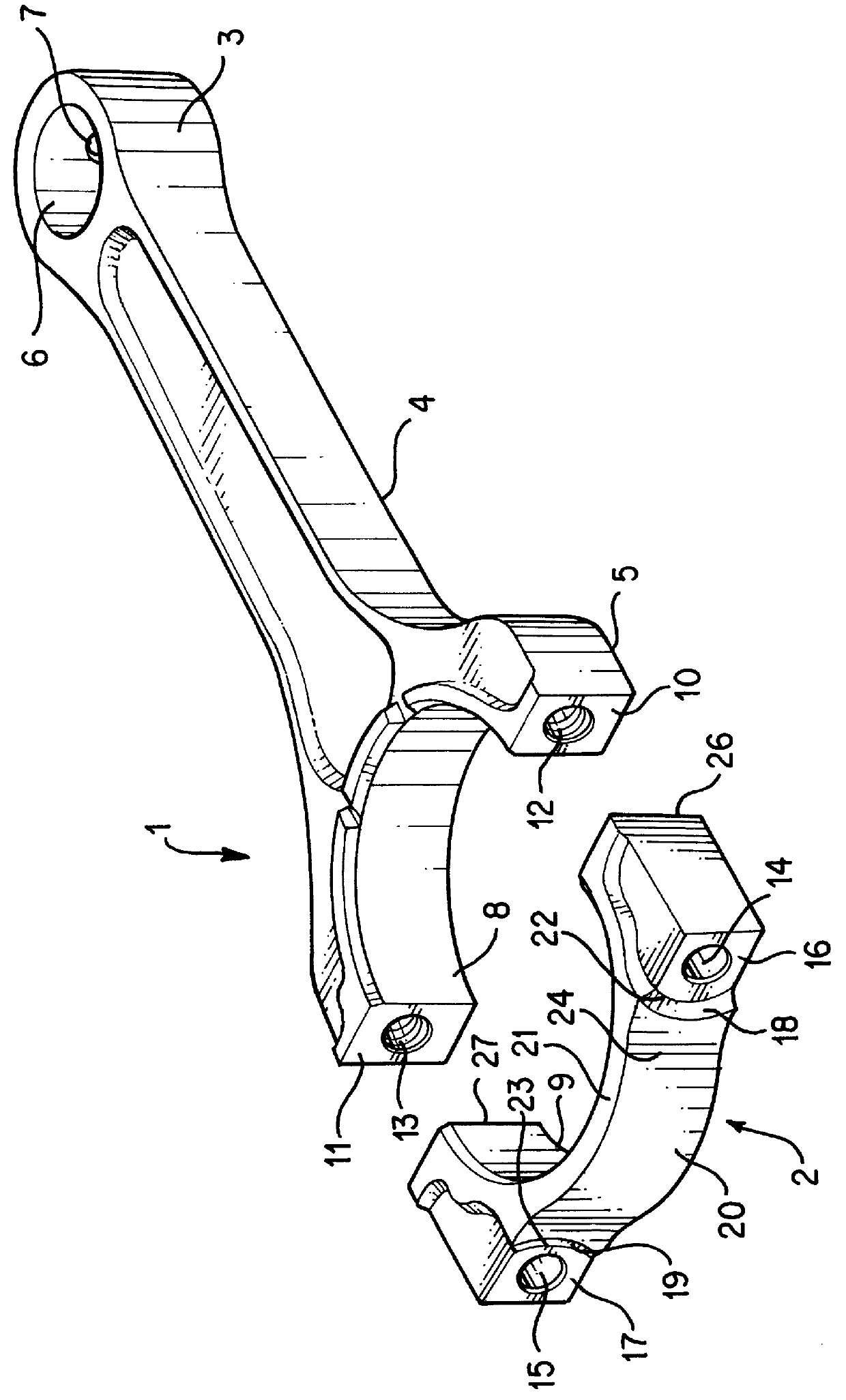
The connecting rod assembly is shown in perspective in FIG. 1. For purposes of this description, the assembly is shown without the bolts which are inserted through bores 12, 13, 14 and 15. Such bolts and other mechanical fasteners are known in the art. Thus, a description is not deemed necessary for purposes of the specification. The connecting rod assembly consists of two pieces 1, 2. For purposes of this description the larger piece 1 is referred to as the connecting rod or rod and the smaller piece 2 is referred to as the bearing cap or cap. The larger piece 1 consists of a small end 3, a beam portion 4 and a large end 5 which provides a portion of the opening in the large end 8.

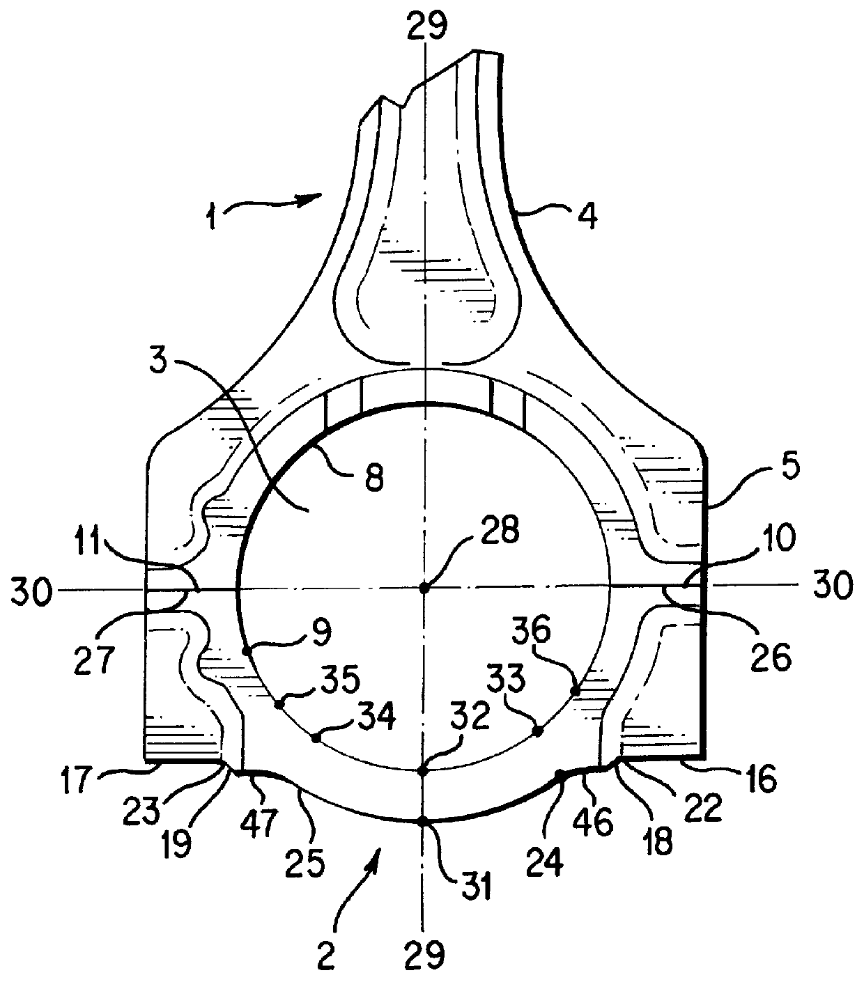
The bearing cap 2 provides the remainder 9 of the enclosure 37 (shown in FIG. 2) which is the cylindrical opening for enclosing the journal of a crankshaft. While the wrist pin of a piston may be inserted in the enclosed small bore 6, the complicated structure of a crankshaft prohibits such an insertion i...


PUM

PropertyMeasurementUnit
thicknessaaaaaaaaaa
RIaaaaaaaaaa
radiusaaaaaaaaaa

Abstract

A light-weight bearing cap for attaching a connecting rod to a journal of a crankshaft pin has two longitudinally extending shoulders separated by an arcuate span conforming to the shape of the journal The shoulders are adapted to receive fasteners which connect mating surfaces of the connecting rod to those of the bearing cap. Mass is conserved by ensuring that the inner and outer arcuate surfaces are shaped as arcs of non-concentric circles such that the maximum thickness of the span occurs at the bisecting points of the respective arcs and the minimum thickness of the span occurs in the region between the shoulders and the maximum thickness. The thickness where the machined surface on the shoulder is located is greater than in the region between the shoulder and the region of maximum thickness.

Description

1. Field of the InventionThe present invention relates generally to the field of connecting rods and their bearing caps which transfer the pressure of combustion from reciprocating pistons to the rotary motion of the crank shaft and, more particularly, to connecting rods and their bearing caps which have been obtained by forging the rod and the cap as a single piece from a powder metal sintered preform and then separating them by cracking the cap from the rod.2. Description of the Related ArtConnecting rods connect the reciprocating piston to the rotating crankshaft. The connecting rod assembly must be sturdy and complex to bear the load of combustion while undergoing the reciprocating and rotary motions. The assembly layout has three basic parts, a small end for connection to the piston, a big end for connection to the crankshaft and a beam connecting the ends. The small end has a cylindrical hole which receives a steel pin ("wrist" pin). The wrist pin is mounted in the opposed sid...

Claims


Application Information

Patent Timeline
Patent Type & Authority Patents(United States)
IPC IPC(8): B23D31/00F16C9/00F16C9/04
CPCB23D31/003F16C9/04F16C9/045Y10T74/2162Y10T74/2142
Inventor LANTZ, KENNETH A.TOFFOLO, JASON L.
Owner HONDA MOTOR CO LTD
Why Eureka
Try Eureka