Compact spectrometer device

Inactive Publication Date: 2000-05-02
VIAVI SOLUTIONS INC
View PDF7 Cites 241 Cited by
  • Summary
  • Abstract
  • Description
  • Claims
  • Application Information

AI Technical Summary

Benefits of technology

It is a primary object of the present invention to provide a color measuring sensor assembly that

Problems solved by technology

While dispersion-based devices can be effectively used in some applications, they have the disadvantage of being easily knocked out of alignment during use, and thus not suitable for more rigorous applications in the field.
These filter-based techniques are limited for practical reasons to use in low resolution spectral measurements of a few bands of light and to non-contiguous bands only.
The use of linear variable filters in spectrometer devices has been limited because of fundamental packaging problems.
Depositing an optical coating on the surface of a detector to form an LVF is problematic because of the delicate surface and w

Method used


Image

  • Compact spectrometer device
  • Compact spectrometer device
  • Compact spectrometer device

Examples


Embodiment Construction

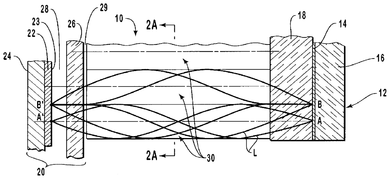
The present invention is directed to a color measuring sensor assembly that can be employed in a spectrometer device such as a calorimeter that is compact and rugged. The sensor assembly generally includes an optical filter, an optical detector array, and a plurality of lenses disposed in at least one row between the optical filter and the optical detector. During operation of the sensor assembly, light beams propagating through the lenses, from the optical filter to the detector, project an upright, noninverted image of the optical filter onto the photosensitive surface of the detector. Various aspects of the sensor assembly of the invention will be discussed as follows.

Referring to the drawings, wherein like structures are provided with like reference designations, the drawings only show the structures necessary to understand the present invention. Additional structures known in the art have not been included to maintain the clarity of the drawings.

FIG. 1 is a schematic depiction ...


PUM


Abstract

A color measuring sensor assembly includes an optical filter such as a linear variable filter, and an optical detector array positioned directly opposite from the optical filter a predetermined distance. A plurality of lenses, such as gradient index rods or microlens arrays, are disposed between the optical filter and the detector array such that light beams propagating through the lenses from the optical filter to the detector array project an upright, noninverted image of the optical filter onto a photosensitive surface of the detector array. The color measuring sensor assembly can be incorporated with other standard components into a spectrometer device such as a portable calorimeter having a compact and rugged construction suitable for use in the field.

Description

1. The Field of the InventionThe present invention is related to optical devices for measuring light. In particular, the present invention is related to a compact spectrometer device for use in color discrimination or evaluation.2. The Relevant TechnologyOptical devices known generally as spectrometers have been developed for measuring and analyzing the spectral or color content of electromagnetic radiation in the frequency range or spectrum of optical wavelengths. These include from ultraviolet, through visible, to near-infrared wavelengths, which include the portion of the electromagnetic spectrum producing photoelectric effects, referred to herein as "light." Various kinds of opto-electronic devices are used for both imaging applications, as by inspecting the spectral reflectance characteristics of a two-dimensional object, and for non-imaging applications.Spectrometric measurements of light are performed in basically two ways, including dispersion-based techniques and filter-bas...

Claims


Application Information

Patent Timeline
IPC IPC(8): G01J3/51G01J3/12G01J3/26G01J3/28G01J3/02
CPCG01J3/02G01J3/0208G01J3/0256G01J3/513G01J3/26G01J3/51G01J3/0259G01J3/2803
Inventor ANTHON, ERIK W.
Owner VIAVI SOLUTIONS INC
Why Eureka
Try Eureka