Rolling screen

a screen and roller technology, applied in the field of roller screens, can solve the problems of insufficient strength of the shaft, insufficient arrangement of the screen case, and substantial deformation

Inactive Publication Date: 2000-05-09
TOMITA KATSUAKI
View PDF24 Cites 65 Cited by
  • Summary
  • Abstract
  • Description
  • Claims
  • Application Information

AI Technical Summary

Problems solved by technology

This may lead to an inconvenience that the screen may be caused to flare at a central part thereof.
This leads to a problem that the screen case may not be adequately arranged within a small depth of a frame of an opening of a building, for example, within a small depth of inner casing of an opening of a door or window.
The take-up shaft cannot therefore be provided with sufficient strength, possibly resulting in a substantial deformation due to flexion caused upon winding out the screen or during use of the screen.
This deformation in turn results in waving of the screen, thereby making it impossible to fully achieve the object, that is, the prevention of entry of insects.
In particular, as the length of a take-up shaft of a small outer diameter becomes greater, the take-up shaft tends to become more liable to arching before transmission of sufficient rotating force to the take-up shaft upon winding out the screen.
It may hence become no longer possible to wind out the screen in some instances.
Openings therefore tend to occur between the upper and lower edges of the net and the corresponding upper and lower frames of the opening of the building, leading to a problem that the wire screen cannot fully prevent insects from entering the building.
Moreover, the upper and lower edges of the net are more susceptible to stretching and slacking than a central part of the net.
This results in problems that the net may be stored in a folded state upon taking it up on a take-up shaft, and the net yarns are prone to loosening at the upper and lower edges, leading to breakage of the net.
The sewing of tapes such as of aluminum foil or the like however results in a greater thickness at both the upper and lower edges of the net.
As a result, the take-up shaft with the net wound thereon has a greater outer diameter, leading to a problem that a greater screen case must be used for the accommodation of the take-up shaft and the net wound thereon.
Friction is however developed between the reinforced opposite vertical side edges of the net and the corresponding guide rails when the net is caused to extend or is taken up.
Due to this friction, greater operating force is required upon causing the net to extend or retract and especially, significant operating force is required upon causing the net to extend downwards.
The above friction also causes sliding noise upon operating the net in a vertical direction.
Further, when the net is exposed to external pressure and substantially large load is applied to the opposite vertical side edges of the net, the opposite vertical side edges of the net may slip out of the guide rails.
If this happens, it is very difficult to repair the vertical rolling wire screen.
This is certainly very cumbersome for the user.

Method used


Image

  • Rolling screen
  • Rolling screen
  • Rolling screen

Examples


first embodiment

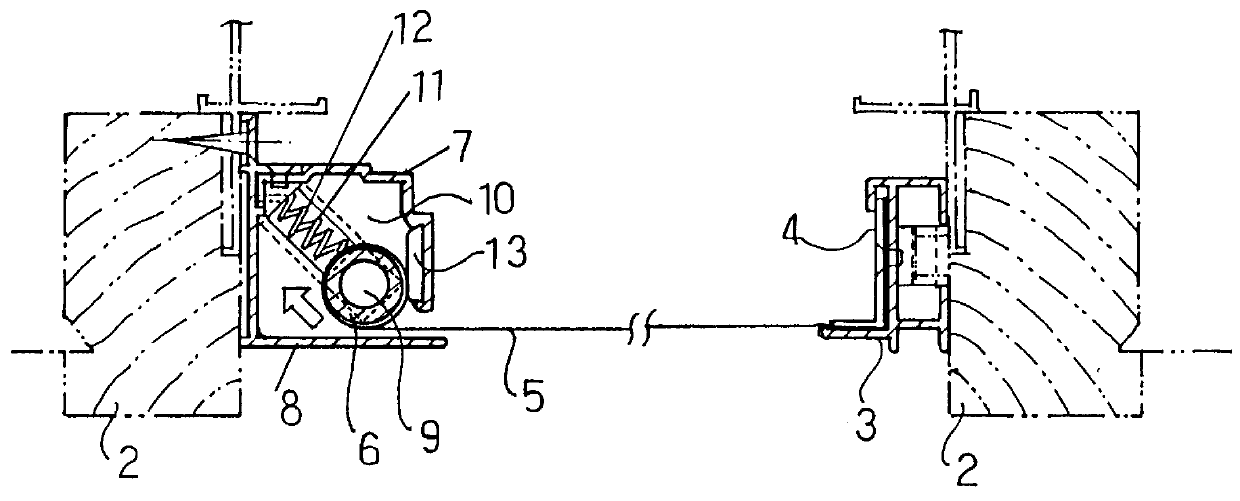
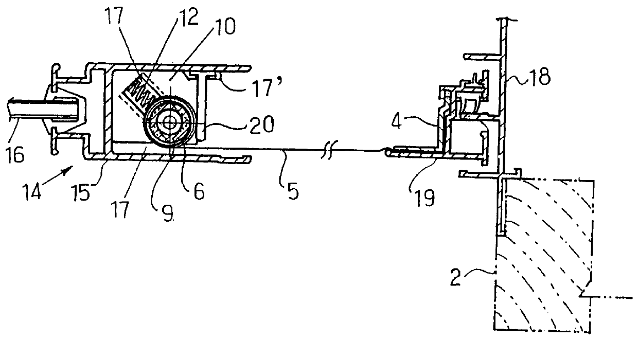
Reference is next had to FIG. 3, where the rolling screen 1 according to the present invention is accommodated within the window end stile 15 of the sliding glass sash 14 in the double sliding sash. The window end stile 15 with a pane fitted therein has an open channel pocket 17 on a side of a jamb 18, and a cover member 19 disposed in engagement with the jamb 18 is engageable with the window end stile 15 so that the open channel pocket 17 can be closed by the cover member 19. The angle 4 to which the one end of the screen 5 is fixedly joined is secured on the cover member 19. The take-up shaft 6 with the screen 5 wound thereon is accommodated within the open channel pocket 17 of the window end stile 15. This take-up shaft 6 is rotatably supported on the brackets 9, which are loosely fitted in the guide grooves 11 of the brackets 10 fixed on the upper and lower ends of the window end stile 15, respectively. Along the guide grooves 11 of the fixed bracket 10, the take-up shaft 6 is m...

second embodiment

The net-shaped flexible screen 5, which is employed in the rolling screen 1 according to the present invention, is brought into engagement, as is depicted in FIG. 10, with the upper fastener 28 on a lower side of the upper thin film 42 and also with the lower fastener 28 on an upper side of the lower thin film 42. Each fastener 28 is composed of hoops 28a and synthetic resin bristles 28b implanted in the hoops 28a. Each synthetic resin bristle 28b terminates in a grip 28c having a larger diameter than the bristle 28b. When the take-up shaft 6 rolls over the fasteners 28 with the net-shaped flexible screen 5 interposed therebetween, the net-shaped flexible screen 5 is pressed against the fasteners 28 so that the grips 28c formed at the free ends of the synthetic resin bristles 28b enter the mesh openings of the screen 5. As a consequence, the bristles 28b are hooked on the warp yarns 43a and the weft yarns 43b of the screen 5. In this manner, the net-shaped flexible screen 5 is held ...


PUM


Abstract

A rolling screen comprises a screen case, a take-up shaft arranged rotatably about a central axis thereof within the screen case, and a screen wound on said take-up shaft so that the screen can be wound out of said screen case. The take-up shaft is normally biased in a screen-winding direction by a torsion spring. An outer peripheral surface of the screen wound on the take-up shaft is always maintained in contact with an inner wall of the screen case, said inner wall being located in a direction of winding-out of the screen, by pulling force applied to the screen upon extension of the screen or resilient force of a pressing spring when the screen is wound out or wound in.

Description

a) Field of the InventionThis invention relates to a rolling screen with a screen such as an insect net or a sunshade cloth stored within a screen case. The screen is wound on a take-up shaft rotatably held within the screen case. Accordingly, the screen can be automatically arranged extending over an opening of a building or the like while winding it out of the screen case. When the screen becomes no longer needed, it can be wound back into the screen case by taking it up on the take-up shaft.b) Description of the Related ArtConventional rolling screens include those having a screen case arranged inside a window frame or the like. The screen case is provided with a hollow take-up shaft rotatably arranged inside the screen case. A screen, such as an insect net or a sunshade cloth, is wound on the take-up shaft so that the screen is stored within the screen case. When the screen is needed, the screen is wound out of the screen case so that it is automatically arranged extending over ...

Claims


Application Information

Patent Timeline
Patent Type & Authority Patents(United States)
IPC IPC(8): E06B9/52E06B9/54E06B9/56E06B9/58
CPCE06B9/54E06B2009/543
Inventor TOMITA, KATSUAKI
Owner TOMITA KATSUAKI
Why Eureka
Try Eureka