Free standing, three dimensional, multi-chip, carrier package with air flow baffle

a carrier package and air flow baffle technology, applied in the direction of electrical apparatus contruction details, printed circuit non-printed electric components association, electrical apparatus casings/cabinets/drawers, etc., can solve the problems of consuming valuable card or board surface area, occupying valuable space in the module package, and limited cooling of the components mounted on the carrier

Inactive Publication Date: 2000-05-09
IBM CORP
View PDF17 Cites 94 Cited by
  • Summary
  • Abstract
  • Description
  • Claims
  • Application Information

AI Technical Summary

Problems solved by technology

However, the use of heat sinks takes up valuable space in a module package.
In addition, chip and component carriers have been fabricated and packaged in a planar fashion which consumes valuable card or board surface area.
The cooling of the components mounted on thes...

Method used


Image

  • Free standing, three dimensional, multi-chip, carrier package with air flow baffle
  • Free standing, three dimensional, multi-chip, carrier package with air flow baffle
  • Free standing, three dimensional, multi-chip, carrier package with air flow baffle

Examples


Embodiment Construction

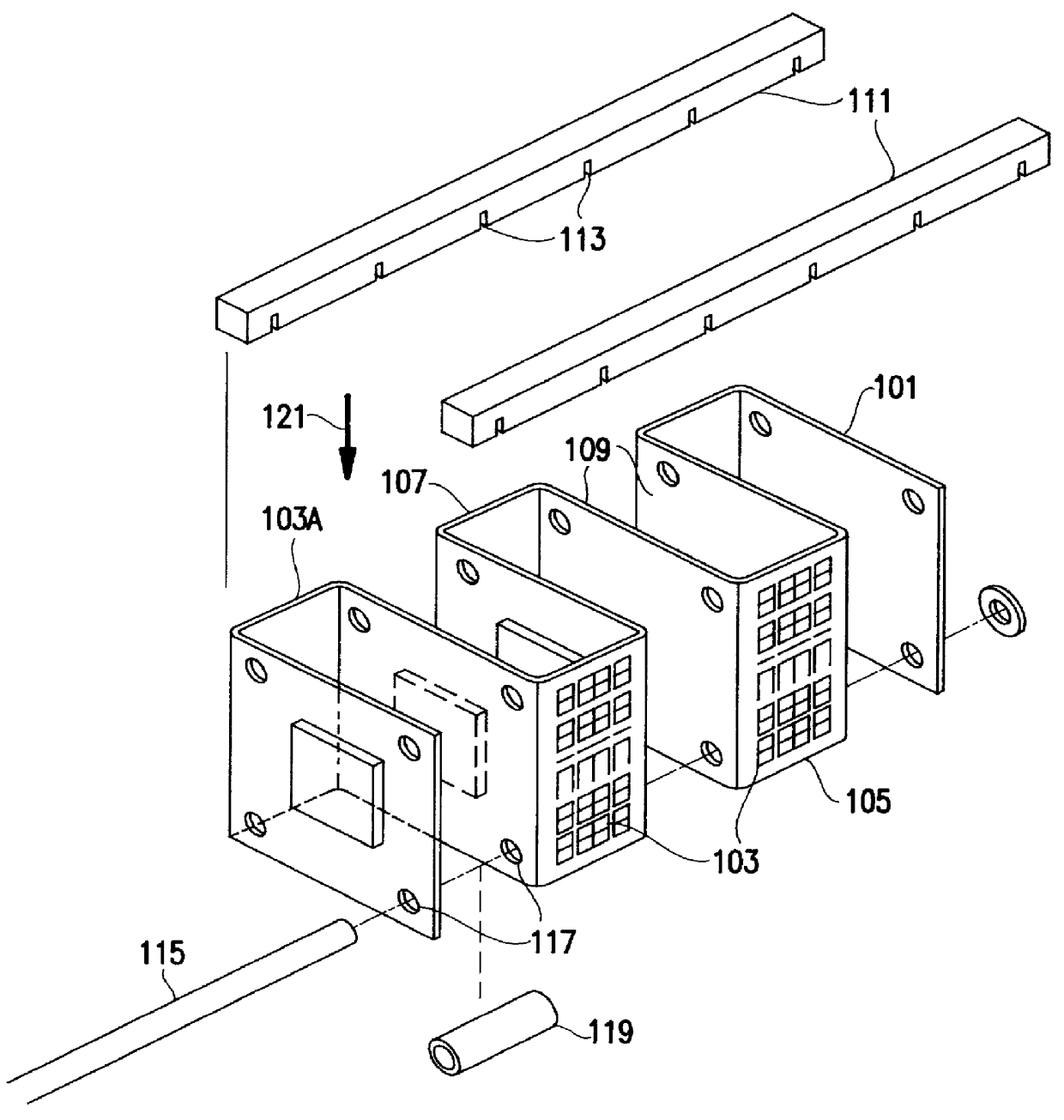
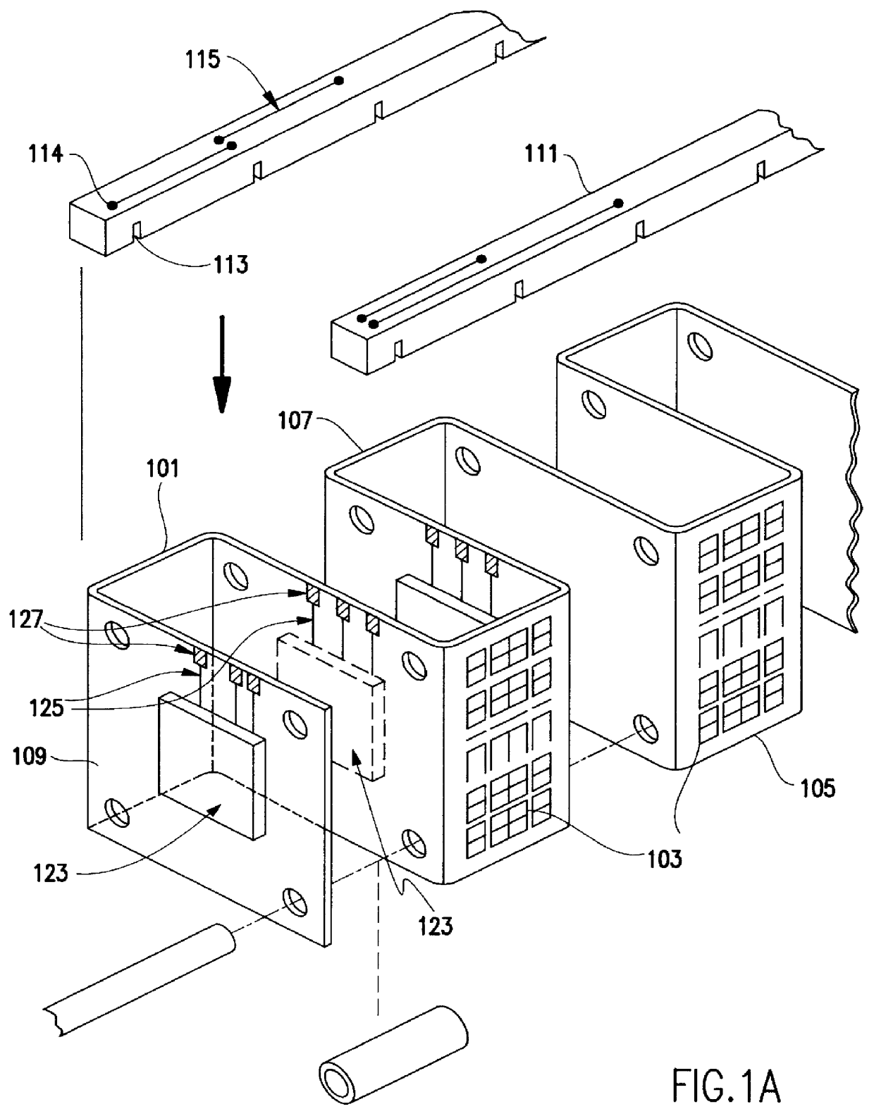
Referring now to the drawings, and more particularly to FIG. 1, there is shown one embodiment of the inventive chip carrier in which the flexible carrier 101 is formed in a serpentine shape. The serpentine shape of the carrier in this figure forms multiple rectangles or squares. Contact pads, in the example illustrated, dendritic pads 103, are located on the outer edges of folds of the flexible carrier 101 for mounting other components or mounting the module to a substrate. Dendritic pad connection sites may also be placed in flat regions 109 between edges 105 and 107 for component mounting.

Additionally, these contact pads may be surface component mounting contact pads, flex circuit contact pads, or flex to substrate contact pads. The outer surface of the opposite side of the serpentine, identified in FIG. 1 as 103A, can be used for mounting other substrates, circuit boards, modules or chips to form a sandwich type structure with the serpentine structure in the middle of the resulta...


PUM


Abstract

An efficient cooling mechanism for a multi-chip carrier can be provided while conserving board surface area. Flexible circuitized material is used to form multi-chip carriers with air baffle capability. The flex is folded or curved into the desired shape and held in position with a support structure. Bonding sites for chips are located on regions through the carrier. Shapes which provide air baffle capabilities include coils, spring-like coils and serpentines.

Description

1. Field of the InventionThe present invention generally relates to multi-chip carriers and, more particularly, to carrier packages which provide for air flow in cooling electronic components.2. Background DescriptionChip carriers have been constructed with heat sinks to provide cooling for chips. However, the use of heat sinks takes up valuable space in a module package. In addition, chip and component carriers have been fabricated and packaged in a planar fashion which consumes valuable card or board surface area. The cooling of the components mounted on these carriers is limited to air flow across the horizontal plane on which the carrier is mounted. Vertical space is often reserved for some kind of heat fin or heat dissipating structure to radiate heat away from the components. Special off-substrate air directing channels or structures are often built within a computing machine to increase air flow efficiencies. This uses valuable space within the machine which could have been o...

Claims


Application Information

Patent Timeline
IPC IPC(8): H01L23/34H01L23/52H01L23/538H01L23/467H01L25/065H05K1/18
CPCH01L23/467H01L23/5385H01L25/065H01L25/0657H05K1/189H01L2225/06575H01L2225/06579H01L2924/0002H01L2225/06589H01L2924/00
Inventor INGRAHAM, ANTHONY P.KEHLEY, GLENN L.SATHE, SANJEEV B.SLACK, JOHN R.
Owner IBM CORP
Why Eureka
Try Eureka