Method and apparatus for rotary mining

Inactive Publication Date: 2000-05-23
FAMILY TRUST OF ALLEN J GOURLEY & FAITH KIMKO GOURLEY THE +1
View PDF9 Cites 46 Cited by
  • Summary
  • Abstract
  • Description
  • Claims
  • Application Information

AI Technical Summary

Benefits of technology

The present invention represents a substantial advance over prior systems and methods for mining. The present invention has the advantage that it can remove subterranean material relatively quickly without jeopardizing human safety underground. The present invention has the further advantage that it is capable of removing material from thin seams which often contain valuable materials which cannot otherwise be mined cost effectively. The present invention also has the advantage that it can be used for special applications such as to remove material from edges, corners, and EPA sensitive seams. The present invention also has the advantage that mined material can be continuously loaded as it is mined. The present invention has the further advantage that excavated cylinders from which material has been mined can be used for waste disposal. The present invention also has the advantage that oil and gas can be won by creating large diameter disks in "pay zones."

Problems solved by technology

Sophisticated and expensive mining machinery loosens the material and transports the material to the surface, but personnel are required to work with them in dangerous underground conditions.
However, strip mining also requires the use of expensive machinery to remove the overburden and the material.
Furthermore, because the overburden is removed above the seam, strip mining has an adverse environmental impact on the area being mined and returning a strip mine site to its original condition can be costly.
Strip mining also has the disadvantage that it may not be economically feasible to remove the overburden above deep portions of a seam that varies in depth.
Such a situation may dictate the use of expensive highwall mining techniques that are designed to remove the material from the deep portion of a seam when removal of overburden is no longer economically feasible.

Method used


Image

  • Method and apparatus for rotary mining
  • Method and apparatus for rotary mining
  • Method and apparatus for rotary mining

Examples


Embodiment Construction

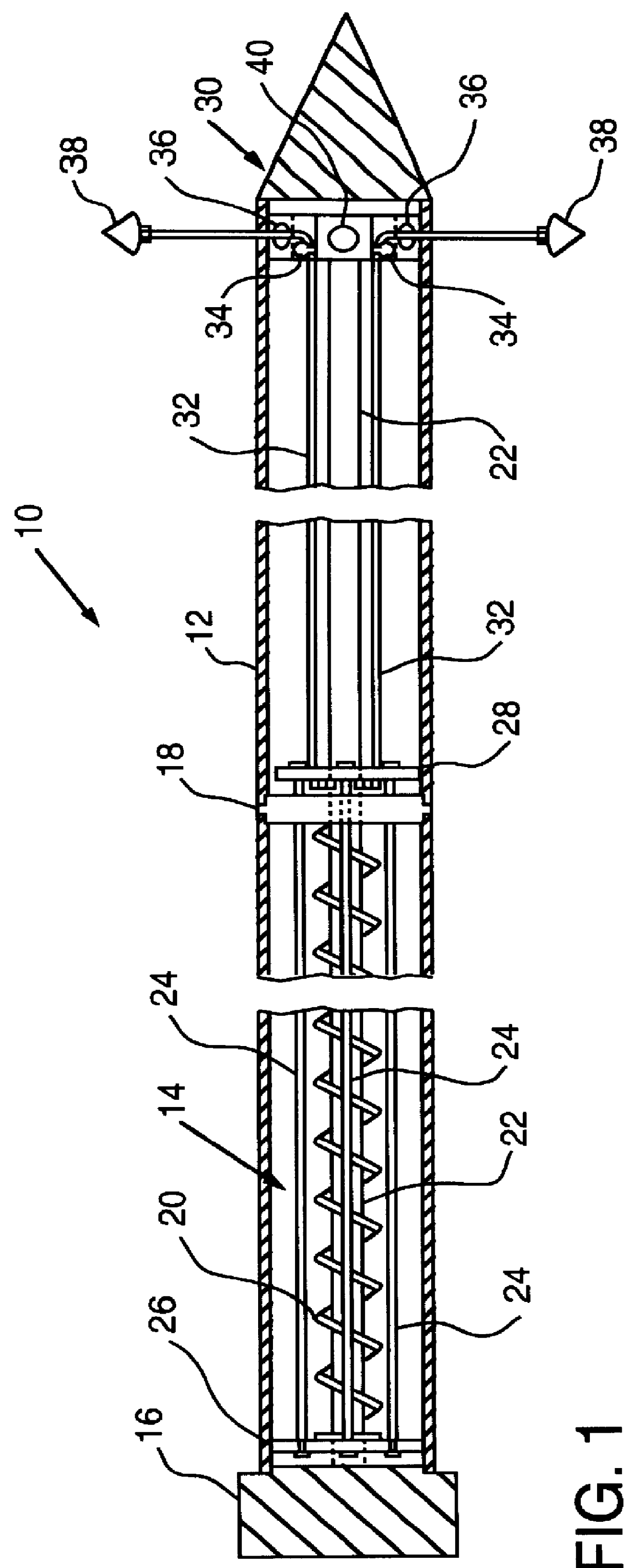
FIG. 1 is a cross-sectional illustration of a preferred embodiment of a rotary mining device 10. The device 10 includes an elongated cylindrical housing 12 which is constructed of a durable material such as, for example, steel. The housing 12 includes a compression chamber 14 which is sealed at one end by a damper cap 16 and at the other end by a damper base 18. The compression chamber 14 also includes a spring 20 which is coiled around an air shaft 22. The air shaft 22 is connected to the damper cap 16. A plurality of drop rods 24 are connected to a top disk 26 at an end of the housing 12 closest to the damper cap 16. The drop rods 24 extend through the damper base 18 and are connected to a bottom disk 28. The damper base 18 has openings which allow the drop rods 24 to extend through the damper base 18 while sealing the compression chamber 14.

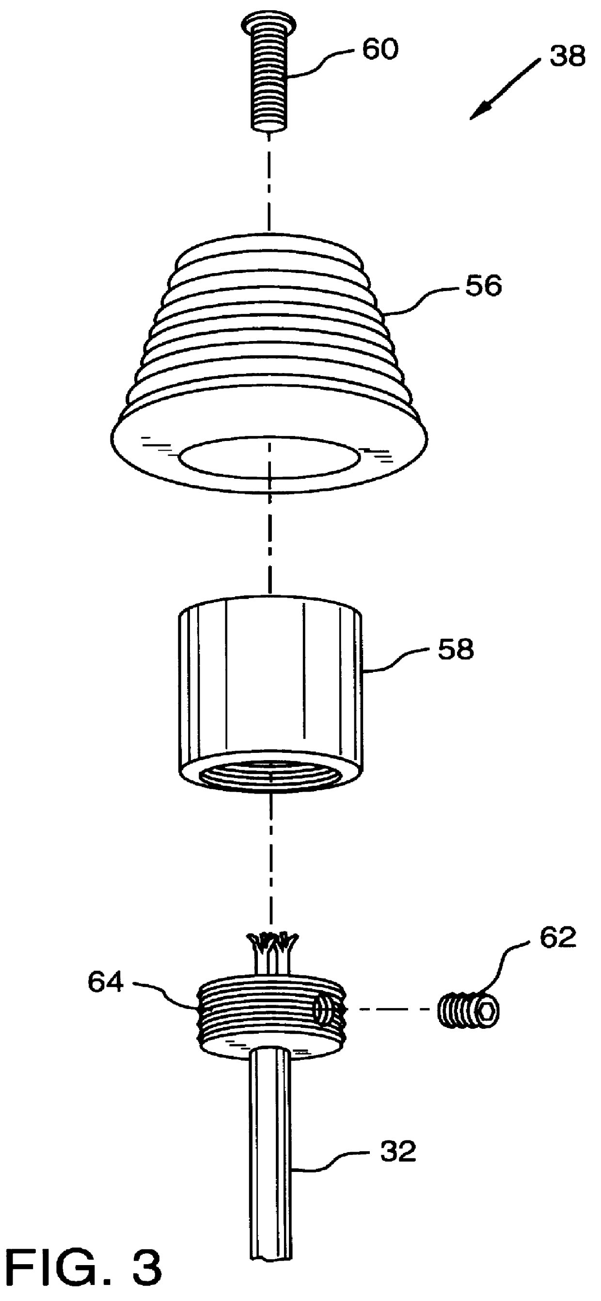
The air shaft 22 extends through the damper base 18 and the bottom disk 28 and is connected to a spin tip assembly 30. The spin tip assembly ...


PUM


Abstract

The present invention is directed to a rotary mining apparatus. The apparatus includes an elongated housing with a leading end and an opposite trailing end. The apparatus also includes a compression device coupled to the housing. The apparatus further includes a plurality of cables extending along the housing. Each of the cables has an end connected to the compression device. The apparatus also includes a plurality of cutting devices attached to the cables at ends of the cables opposite the ends connected to the compression device. The present invention is also directed to a method of removing subterranean material. The method includes the step of inserting a rotary mining device having radially extendable cutting devices into a subterranean shaft. The method also includes the steps of rotating the mining device such that the cutting devices contact the sides of the shaft and extending the cutting devices into the sides of the shaft.

Description

I. CROSS REFERENCE TO RELATED APPLICATIONS(Not Applicable)II. STATEMENT REGARDING FEDERALLY SPONSORED RESEARCH OR DEVELOPMENT(Not Applicable)III. BACKGROUND OF THE INVENTION1. Field of the InventionThe present invention is directed generally to a method and apparatus for mining, and, more particularly, to a method and apparatus for rotary mining.2. Description of the BackgroundIn conventional mining, different techniques are employed to remove the desired subterranean material. One technique that is commonly employed for mining coal from seams that are relatively deep beneath the surface involves a network of underground shafts and passages. Sophisticated and expensive mining machinery loosens the material and transports the material to the surface, but personnel are required to work with them in dangerous underground conditions.Another technique, known as strip or surface mining, is used to remove valuable material from seams that are relatively close to the surface. In strip minin...

Claims


Application Information

Patent Timeline
IPC IPC(8): E21B7/00E21B7/28E21B10/26E21B10/32E02D5/34E02D5/44
CPCE21B10/32E21B7/28E02D5/44
Inventor GOURLEY, ALLEN JAMESGOURLEY, LARRY PARKS
Owner FAMILY TRUST OF ALLEN J GOURLEY & FAITH KIMKO GOURLEY THE
Why Eureka
Try Eureka