Eureka AIR delivers breakthrough ideas for toughest innovation challenges, trusted by R&D personnel around the world.

Design method of topology optimization for flexible hinge

a topology optimization and hinge technology, applied in multi-objective optimisation, instruments, cad techniques, etc., can solve the problems of limiting the movement range of the hinge, small rotation flexibility, and difficulty in meeting the three indexes at the same time, so as to improve the performance, improve the rotation flexibility, and improve the effect of rotation precision

Active Publication Date: 2018-07-26
SOUTH CHINA UNIV OF TECH
View PDF7 Cites 30 Cited by
  • Summary
  • Abstract
  • Description
  • Claims
  • Application Information

AI Technical Summary

Benefits of technology

The invention provides a novel flexible hinge that has better performance compared to existing hinges. It has higher rotation flexibility, precision and lower stress level. The hinge's topology configuration is determined based on objective functions and constraint conditions, allowing for the automatic generation of a hinge that meets a given requirement. This new design approach provides a fresh outlook and method for flexible hinge design.

Problems solved by technology

However, owing to the elastic deformation of flexible hinge itself, it is very difficult to meet these three indexes at the same time.
For example, among the convention flexible hinges, straight-circular type flexible hinge and V type flexible hinge have a relatively high rotation precision, but small rotation flexibility and very high stress level, which greatly restrict their movement range.
This makes it difficult to design the flexible hinge with complex configuration and excellent performances.

Method used


Image

  • Design method of topology optimization for flexible hinge
  • Design method of topology optimization for flexible hinge
  • Design method of topology optimization for flexible hinge

Examples


Embodiment Construction

[0028]In order to better understanding the invention, it will be further specified below in combination with accompanying drawings of which implementations are not limited thereby.

[0029]In accordance with FIGS. 1-4, a design method of topology optimization for flexible hinge specifically comprises following steps:

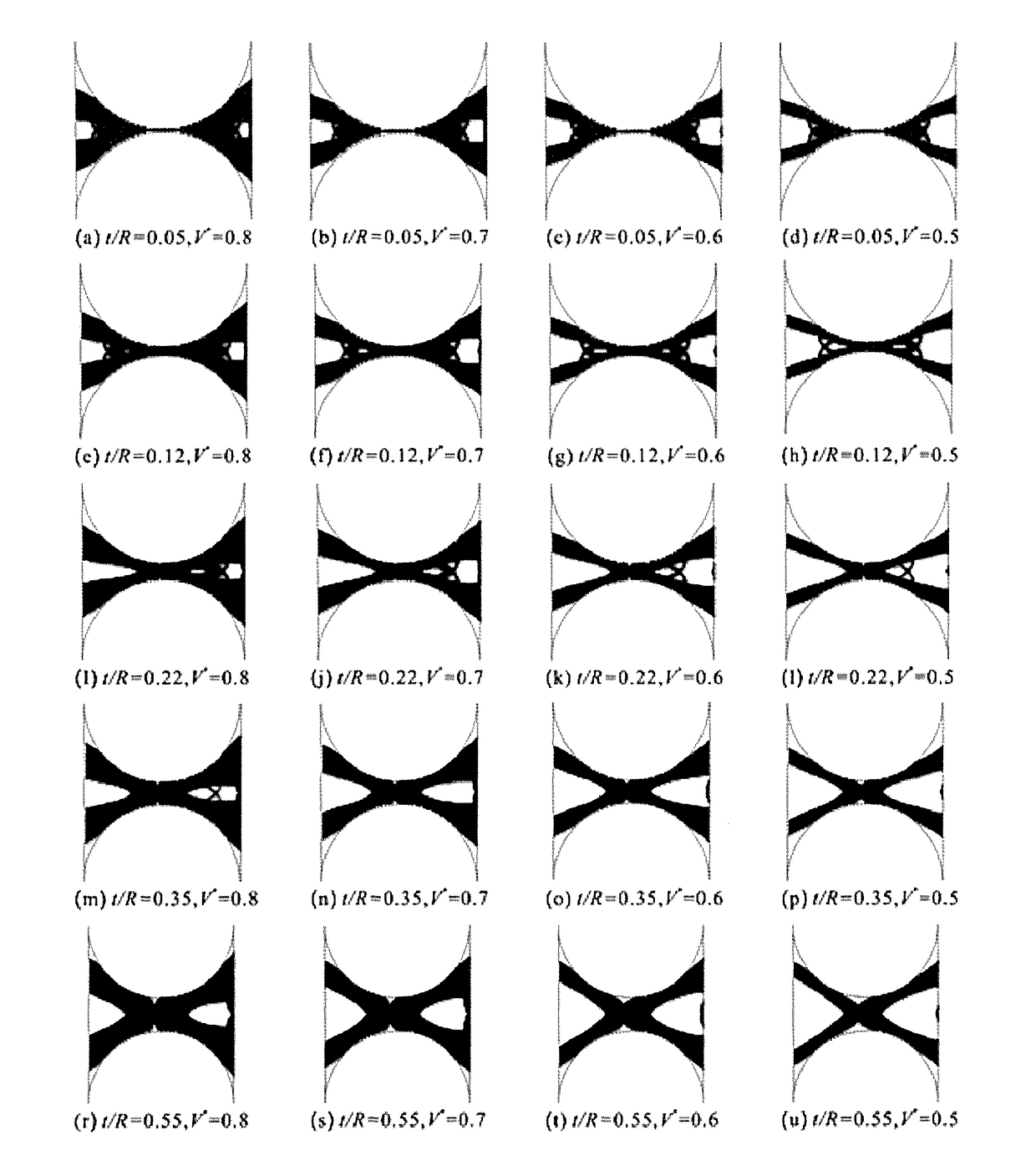
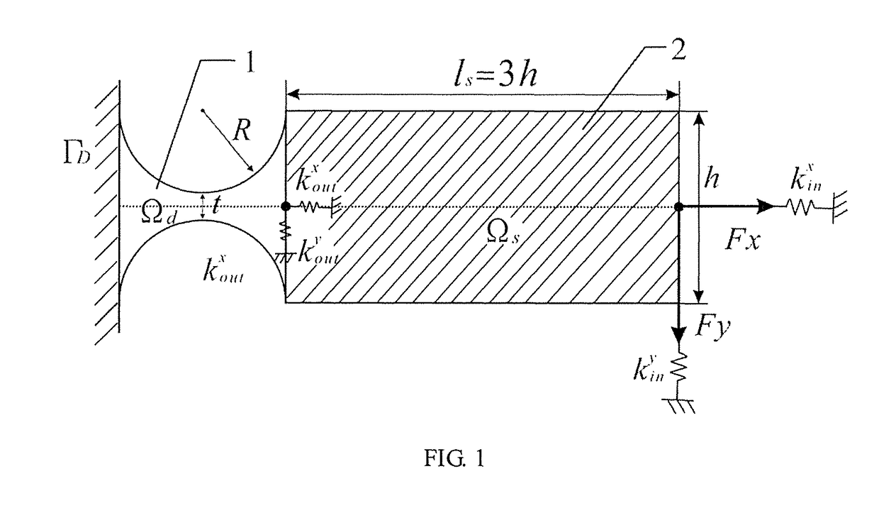
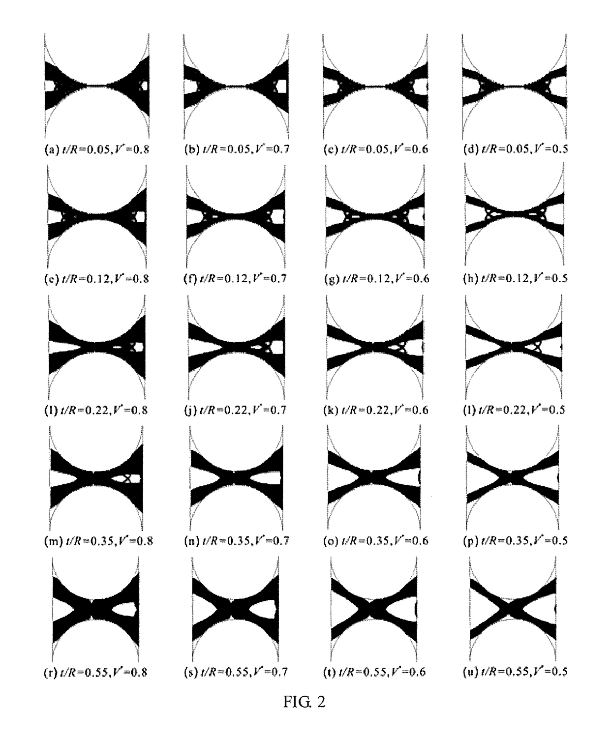
[0030]step 1: establishing a design model of topology optimization for flexible hinge and setting an outline of typical flexible hinge as a design domain. In this embodiment, the outline of a straight-circular type flexible hinge serves as the design domain 1, but the design domains of the invention are not limited thereby. Sizes of design domain 1 and a non-design domain 2 (a rigid component) are defined. A radius R of design domain 1 is set as 40 mm and a minimum thickness t is set as 20 mm. A length of non-design domain ls is set as 300 mm and a thickness is set as 1 mm.

[0031]Step 2: establishing a finite element model of topology optimization for flexible hinge. A Young...


PUM


Abstract

A design method of topology optimization for flexible hinge is disclosed in the invention, comprising following steps: step 1: establishing a design model of topology optimization for flexible hinge, setting an outline of flexible hinge with a typical notch as a shape of design domain and defining a rigid region (non-design domain); step 2: establishing a finite element model of topology optimization for flexible hinge; step 3: establishing a mathematical model of topology optimization problem for flexible hinge based on the finite element model; step 4: calculating a sensitivity of topology optimization problem for flexible hinge; step 5: employing an optimization algorithm to solve the topology optimization problem for flexible hinge, updating a design variable and obtaining a final topology result graph; step 6: according to the final topology result graph obtained by the topology optimization, extracting its outline and obtaining a novel flexible hinge by appropriate modification. Using the method of topology optimization, the invention designs the flexible hinge on a concept level. The novel flexible hinge can be designed with a more complex structure and more excellent performances, having a larger flexibility, a higher precision and a smaller maximum stress.

Description

TECHNICAL FIELD[0001]The invention relates to a field of structural design of flexible hinge, and specifically relates to a design method of topology optimization for flexible hinge.BACKGROUND[0002]A flexible hinge which completes a transmission and a transition of movement and force by using an elastic deformation of itself, is generally processed by wire cutting a piece of board material and is greatly different from a conventional rigid kinematic pair structure. The flexible hinge as the most essential flexible element in a centralized compliant mechanism, its performances make significant influence on the compliant mechanism. Compared with the conventional rigid kinematic pair, the flexible hinge has several advantages such as light weight, zero friction wear, being capable of integration processing and high precision, and it draws extensive attention of scholars home and abroad. The flexible hinge is widely applicable in fields such as precision engineering, instrument measurem...

Claims


Application Information

Patent Timeline
Patent Type & Authority Applications(United States)
IPC IPC(8): G06F17/50
CPCG06F17/5018G06F17/509G06F2217/16G06F30/367G06F30/23G06F2113/24G06F2111/06G06F30/17E05D1/02G06F30/18G06F2111/10G06F1/1652
Inventor ZHANG, XIANMINLIU, MIN
Owner SOUTH CHINA UNIV OF TECH
Why Eureka
Eureka Blog
Learn More