Drum brake system and device

a technology of drum brakes and brake levers, which is applied in the direction of mechanically actuated drum brakes, fluid actuated drum brakes, mechanical apparatus, etc., can solve the problems of greater difficulty in laying out the brake lever, the risk of delaying the parking brake effect in an emergency situation, and the driver's discomfort, so as to eliminate the risk of delaying the parking brake effect and eliminate the discomfort of the driver

Inactive Publication Date: 2000-05-23
NISSHINBO IND INC
View PDF15 Cites 13 Cited by
  • Summary
  • Abstract
  • Description
  • Claims
  • Application Information

AI Technical Summary

Benefits of technology

This invention was designed to resolve the above disadvantages. To that end, an object of the invention is to provide a drum brake device which regulates the stroke increase even when the lining is worn, thereby eliminating any discomfort in the driver's feeling when operating the parking brake lever and eliminating a risk of delaying the parking brake effect.

Problems solved by technology

More clearance requiring the longer stroke not only gives disconcerting feeling to the driver when stepping on the brake pedal but also creates a risk of delaying the parking brake effect in an emergency situation.
Additionally, the clearance is prone to cause unintended contact between the other components, especially when a size of the brake device is smaller, thereby causing a greater difficulty in laying out the brake lever.

Method used


Image

  • Drum brake system and device
  • Drum brake system and device
  • Drum brake system and device

Examples


example 2

Example 2 is another embodiment of the drum brake device of this invention. The components which are virtually the same as in Example 1 are identified with the same reference signs wherein an explanation is omitted here.

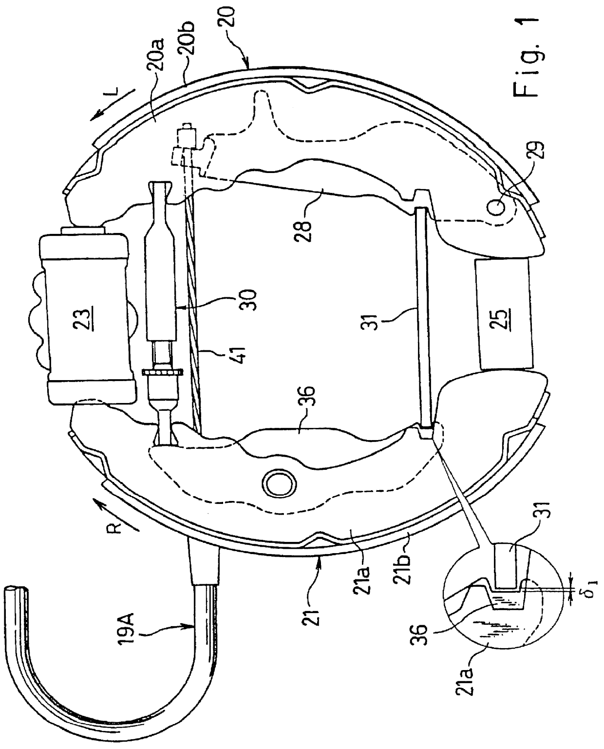
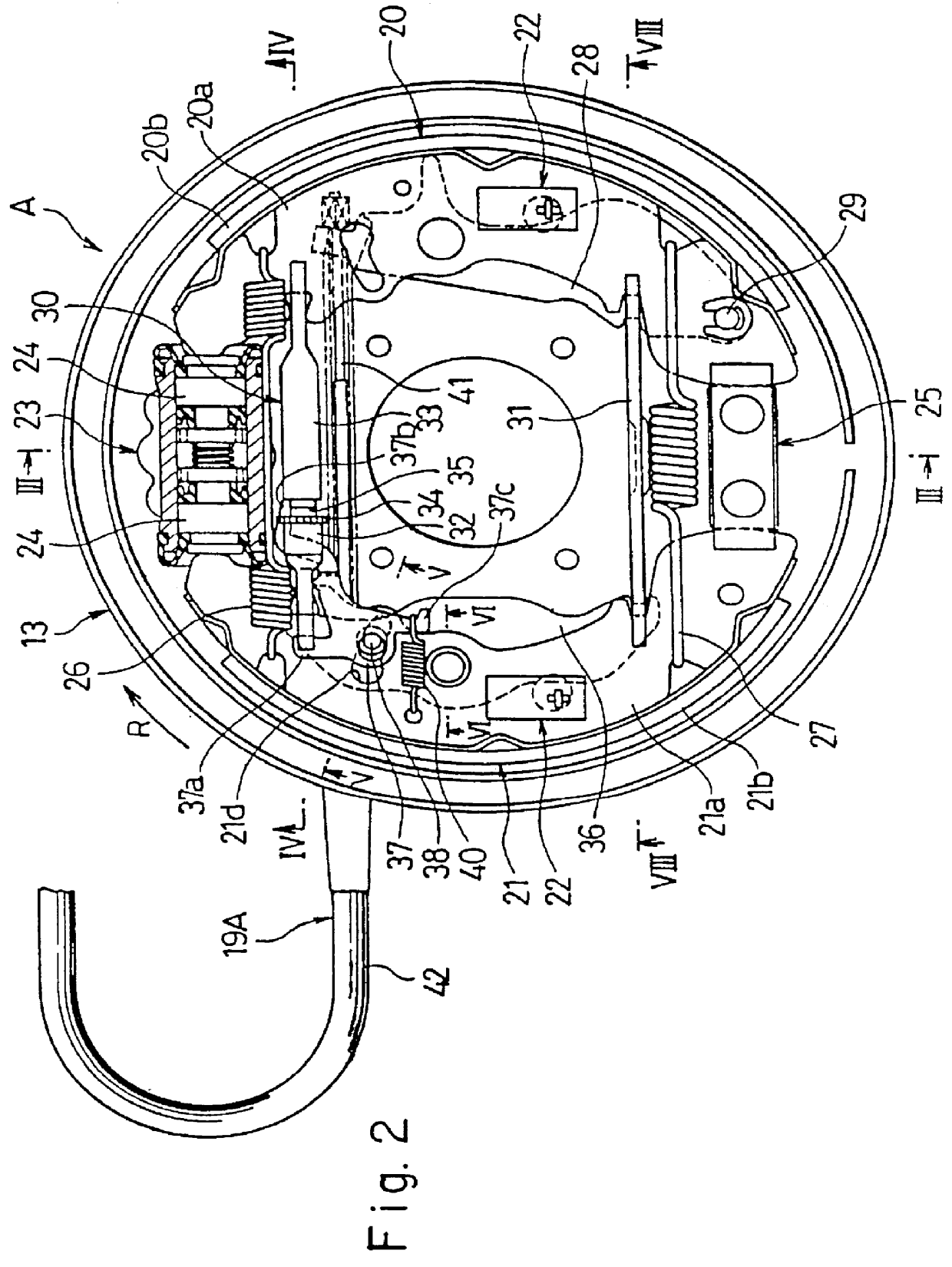
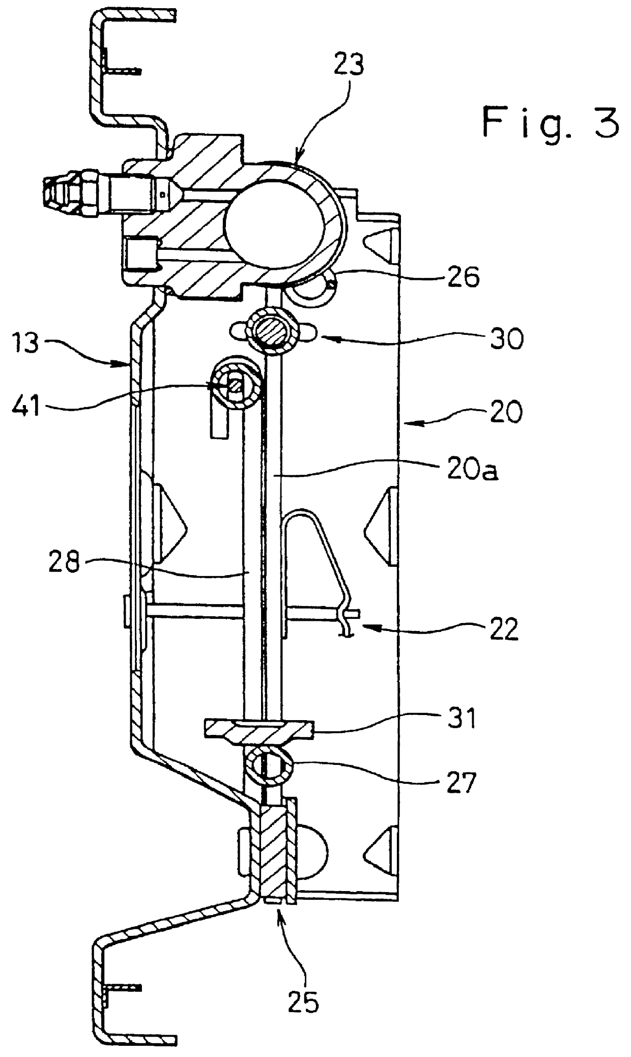
FIG. 11 illustrates the parking brake cables 19A, 19B connected to the drum brake devices A, B and pulled toward the front end of the vehicle just as in the conventional devices. This example illustrates the drum brake devices A, B of Example 1 which are turned 180 degrees with the fluid pressure cylinders 23, 23 below the anchor blocks 25, 25. As explained in Example 1, the drum brakes A, B are symmetrically structured, and the pivot lever 36 is provided on the trailing shoe (brake shoe 21) side.

example 3

FIG. 12 illustrates the installation of the parking brake cables 19A, 19B, where the parking brake cable 19A on the muffler side extends rearwardly is curved to extend toward the front side of the vehicle and the parking brake cable 19B is routed to extend toward the front side of the vehicle. The fluid pressure cylinders 23, 23, are each located oppositely to each other. That is, in one of the drum brake devices, the fluid pressure cylinder is below the anchor block while in the other device, the fluid pressure cylinder is above the anchor block.

example 4

This invention is by no means limited to the embodiments described above. For example, both parking brake cables 19A, 19B can be provided parallel to the axle housing as shown in Japanese Utility Model Publication Number 2-13782.

Having a pivot lever on the trailing shoe side where the lining wears more slowly, does not increase the clearance .delta..sub.1 as much as having a pivot lever on the leading shoe side where the lining wears faster.

Thus, a stroke before effectuating a parking brake is almost the same as brake shoes with new linings even with substantial lining wear. This reduces a chance of creating play in the parking brake operation, thereby eliminating any disconcerting feeling to the driver and any delay in effectuating the parking brake when in an emergency situation.

A longer stroke is not necessary to effectuate the parking brake, which facilitates the layout of the brake lever and enable use of a brake device with a smaller size.

When a muffler obstructs the installat...


PUM


Abstract

A drum brake device is provided in which a stroke before effectuating the parking brake effect of the brake shoes is restricted so that any disconcerting feeling to the driver and any delay in effectuating the parking brake when in an emergency situation are eliminated. The drum brake device includes a pair of the brake shoes 20, 21, a pivot lever 36 pivotally provided at one of the two brake shoes 21, a shoe clearance adjustment device provided between one end of the pivot lever 36 and one end of the brake shoe 20, and a strut provided between the other end of the pivot lever 36 and one end of the brake lever 28, wherein the braking force is transferable between the two brake shoes 20, 21 through the connection with the pivot lever 36. This produces a duo-servo type of brake device. The brake shoe 21 functions as a trailing shoe in which the lining wears slower when the service brake is in operation.

Description

This invention relates to a drum brake device. More specifically, it relates to a drum brake device for a multi-wheel vehicle, such as an automobile, a forklift, and the like, that functions as a leading-trailing (LT) type when the service brake is applied, and as a duo-servo (DS) type when the parking brake is applied. This type of brake is called a dual mode drum brake.FIG. 13 is a plan view of the typical rear chassis of the vehicle. The drum brake devices a, b are located on the right and left ends of the axle housing c. The back plates d, d of the drum brake devices a, b are mounted on each end of the axle housing c. The brake drums e, e are located to be exposed at each wheel side and to cover the two drum brake devices a, b. Each drum brake device includes a fluid operated service brake mechanism, a mechanical parking brake mechanism (neither of them shown in the diagram), and the parking brake cables f, g, both of which extend toward the front side of the vehicle.A dual mode...

Claims


Application Information

Patent Timeline
Patent Type & Authority Patents(United States)
IPC IPC(8): F16D65/14F16D65/56F16D65/38F16D51/24F16D51/00F16D51/50F16D51/52
CPCF16D51/24F16D65/563F16D51/50F16D2125/60
Inventor IKEDA, TAKASHI
Owner NISSHINBO IND INC
Why Eureka
Try Eureka