Snap-in proximal connector for mounting an optic fiber element into a light source system

a technology of optic fiber and proximal connector, which is applied in the field of optic systems, can solve the problems of fiber being easily broken or otherwise damaged, fiber being unprotected and easily broken, and many conventional proximal connectors are affected

Inactive Publication Date: 2000-05-23
MEADOWSTAR ENTERPRISES
View PDF18 Cites 26 Cited by
  • Summary
  • Abstract
  • Description
  • Claims
  • Application Information

AI Technical Summary

Problems solved by technology

However, problems arise in many conventional proximal connectors, particularly those designed for use with a single optic fiber.
For silica fibers having a polymer cladding, excess heat of a conventional connector will destroy the cladding.
However, because the entrance aperture of the single fiber extends from the proximal connector, the fiber is unprotected and easily broken or otherwise damaged after removal from the light source system.
Although such an arrangement protects the proximal end of the optic fiber while also minimizing heat related problems, such is achieved at the ex

Method used


Image

  • Snap-in proximal connector for mounting an optic fiber element into a light source system
  • Snap-in proximal connector for mounting an optic fiber element into a light source system
  • Snap-in proximal connector for mounting an optic fiber element into a light source system

Examples


Embodiment Construction

With reference to the figures, exemplary embodiments of the invention will now be described. These embodiments illustrate principles of the invention and should not be construed as limiting the scope of the invention.

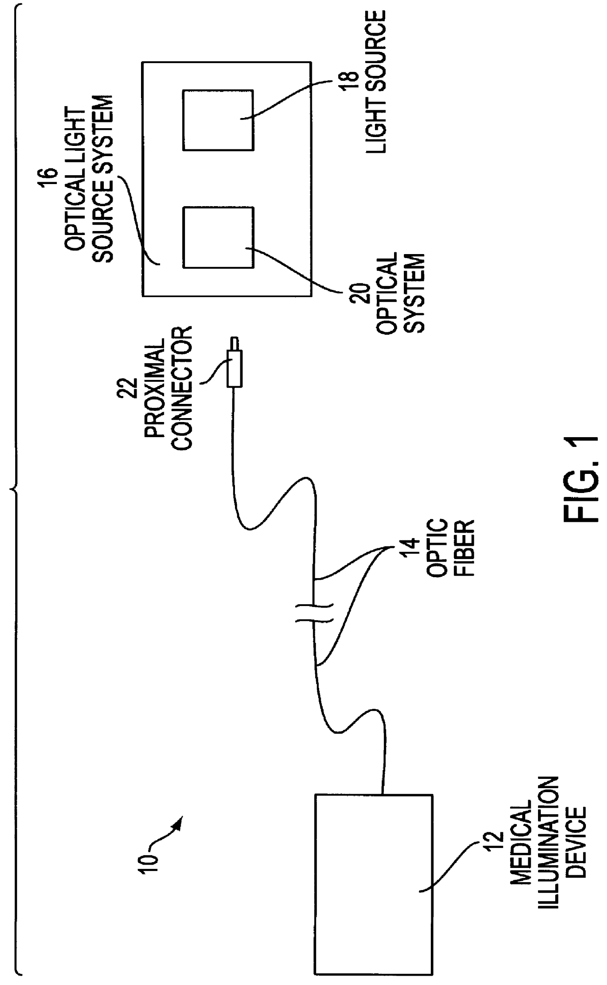
FIG. 1 illustrates an illumination system 10 having, for example, a medical device 12 connected through a single fiber optic 14 to a light source system 16. Medical device 12 may be a surgical headlamp, surgical luminaire, endoscope, borescope, etc. Light source system 16 includes a high intensity light source 18, such as a metal halide or xenon arc lamp, and an optical system 20 for collecting and condensing light from source 18. Optical system 20 may include one or more optical elements such as mirrors, configured, for example, in accordance with the source system described in U.S. Pat. No. 4,757,431.

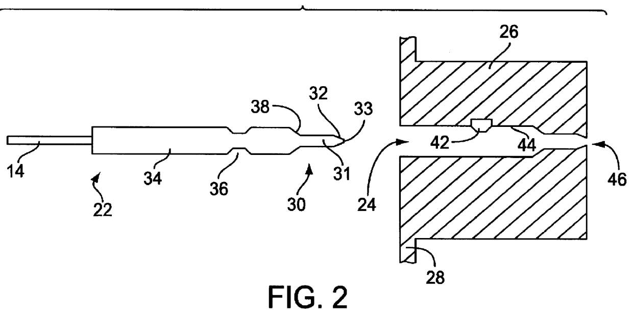
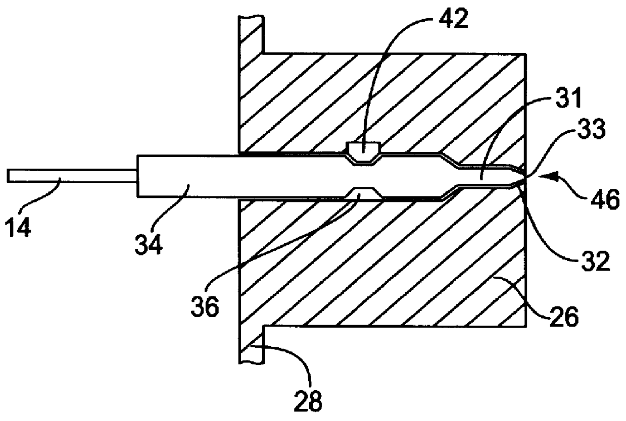
Fiber optic 14 includes a proximal connector 22 configured for "snap" insertion into an aperture formed in a receiving block of a housing of light source system 16. Proxi...


PUM


Abstract

A proximal connector includes a stainless steel, cone-shaped ferrule enclosing a proximal end of the optic fiber element. The ferrule is inserted within a matching aperture of a receiving block, which is also made of stainless steel. The matching shapes of the ferrule and the aperture of the receiving block ensure effective heat transfer from the ferrule into the receiving block. The receiving block may be provided with cooling vanes, and air may be circulated over the cooling vanes, to dissipate heat transferred to the receiving block from the connector. Both ferrule and the aperture are axially symmetric such that any rotation of the proximal connector while inserted into the receiving block does not change the location of the entrance aperture of the optic fiber element. The proximal connector also includes a case having an indented ring. A ball plunger biasing mechanism is mounted within the aperture of the receiving block and is positioned to engage the indented ring only while the proximal connector is fully and securely inserted within the aperture. The plunger prevents accidental removal of the proximal connector while also providing a biasing force for ensuring solid contact between the cone-shaped ferrule and the corresponding portions of the receiving block to further facilitate heat conduction. The concept may be extended to provided adaptor connectors which couple such proximal connectors to an appropriately configured receiving block.

Description

1. Field of the InventionThe invention generally relates to optical systems for coupling light into a single optic fiber or fiber bundle and, in particular, to connector assemblies for connecting a single optic fiber or fiber bundle into the housing of a light source system.2. Description of Related ArtA variety of light source systems have been developed for coupling light from a high intensity light source such as an arc lamp into an optical fiber bundle or single optical fiber. The light coupled into the bundle or single fiber may be used, for example, for medical illumination purposes such as for use with a surgical luminaire, headlamp, endoscope or borescope.Typically, a proximal end of the single fiber or fiber bundle is mounted within a proximal connector for insertion into a slot or aperture within a housing containing the light source. A distal end of the single fiber or fiber bundle is connected to an application device, i.e., a surgical luminaire, endoscope, etc. Typicall...

Claims


Application Information

Patent Timeline
IPC IPC(8): G02B6/38G02B6/42G02B6/36A61B1/06
CPCG02B6/3814G02B6/4296G02B6/3893G02B6/4292G02B6/3869G02B6/3846
Inventor ROLLER, THOMAS W.LI, KENNETH K.
Owner MEADOWSTAR ENTERPRISES
Why Eureka
Try Eureka