Cell culture apparatus

a technology of cell culture and apparatus, which is applied in the field of cell culture apparatus, can solve the problems of prone to external contamination, time-consuming, and awkward, and achieve the effect of reducing the risk of contamination and enhancing cell growth

Inactive Publication Date: 2000-05-23
POWELL BIOLOGICAL MACHINES
View PDF18 Cites 38 Cited by
  • Summary
  • Abstract
  • Description
  • Claims
  • Application Information

AI Technical Summary

Benefits of technology

Alternatively, the cell culture vessel may be purpose made for the apparatus in which case it is proposed to dispense with the filling cap and to provide the vessel with an integral air vent and dip tube. These may be moulded or bonded in place. The use of an integral dip tube further reduces the cost and complexity, whilst the risk of external infections whilst connecting the bottle is likewise reduced.
Accordingly another aspect of the invention provides a cell culture vessel / roller bottle, comprising a substantially cylindrical culture vessel, a dip tube formed integrally in said vessel such that fluid may be fed into or withdrawn from the vessel via the said dip tube, and means formed integrally in said vessel to accommodate a microporous vent filter such that air may leave or enter the vessel in order to allow pressure equalisation with the atmosphere as fluid is fed into or withdrawn from from the vessel without allowing the entry of contaminating particles or organisms.
For certain processes that require the introduction of gasses such as carbon dioxide into the roller bottle to enhance cell growth, the vessel vent, (or vent manifold) may be equipped with a valve or closure to prevent loss of the gas to atmosphere by diffusion during culture stages, said valve or closure being temporarily opened to atmosphere to allow pressure equalisation whilst fluids are being pumped into or out of the vessel.
The cell culture vessel is primarily intended for use with the above-described cell culture apparatus. More particularly, the bottles may be connected to the pump tubes prior to sterilisation, thereby further reducing the risk of contamination whilst setting up the apparatus.
Preferably means is provided for tilting the axis of the rotor to cause fluid to run towards the dip tubes. The tilt mechanism is usually only employed when the rotor is stationary. Advantageously, means is provided for preventing accidental tilting, say in the manner of an interlock.
It is advantageous if each cell culture vessel can be removed from the rotor without having to disconnect the fluid connection thereto. This may be required to permit analysis of the culture (whilst in the bottle) using a microscope. This can be readily made possible by providing a sufficient length of tubing between the manifold and the vessel. When the apparatus is in use with the cell culture vessels located in the rotor the excess length of tubing is conveniently wrapped around a neck portion of the cell culture vessel. A clipping system is employed to hold the tube in place. Alternatively a separate tube storage means may be provided on the rotor.

Problems solved by technology

The processing operations such as innoculation, culture medium supply, or harvesting for example which require the flow of fluids into or out of the roller bottle are carried out manually or by expensive mechanical handling systems such as robots.
For large scale production, this process can be awkward, time consuming, and carries the risk of infection of the bottle contents by foreign organisms during handling.
This system is prone to external infection via the rotary seals however, and is in any case mechanically complex and thus expensive.

Method used


Image

  • Cell culture apparatus
  • Cell culture apparatus
  • Cell culture apparatus

Examples


Embodiment Construction

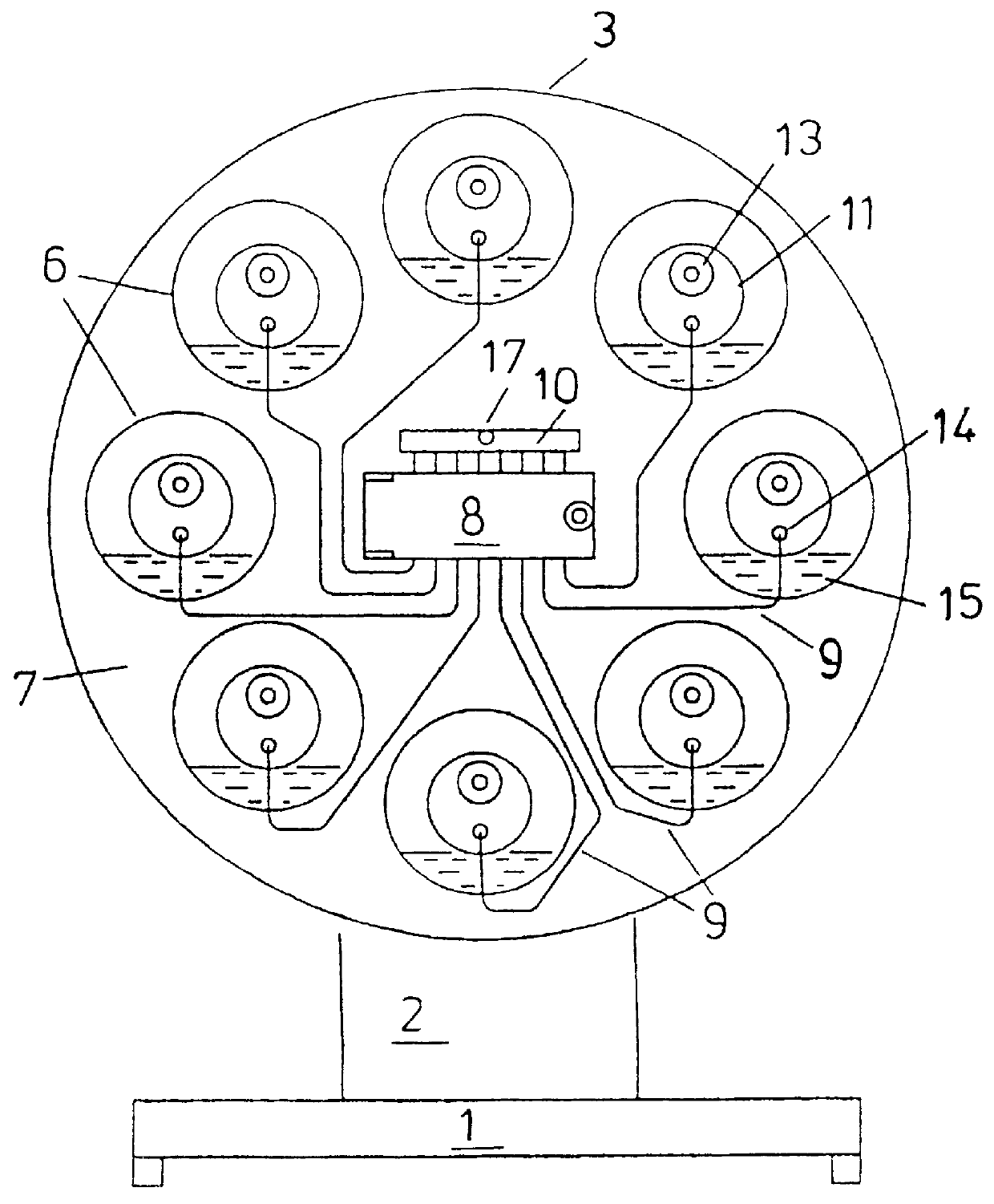
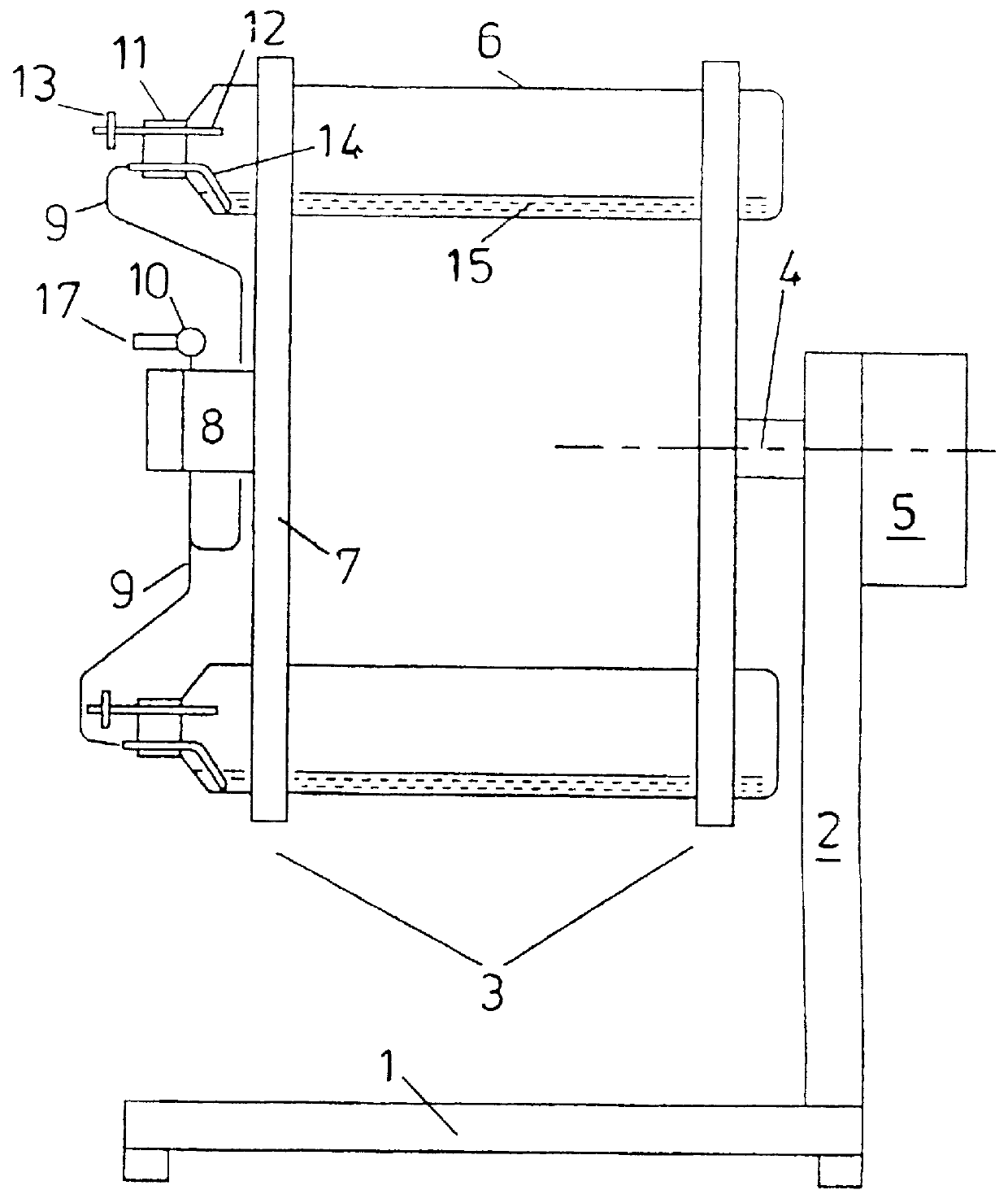
Referring firstly to the drawings of FIGS. 1 to 3, the apparatus comprises a chassis 1 and rear rotor support 2 which supports a rotor 3 that is able to rotate about a horizontal shaft or axis 4. The rotor is driven by a motor and gearbox assembly 5 under the influence of a control system, not shown, such that its speed may be varied.

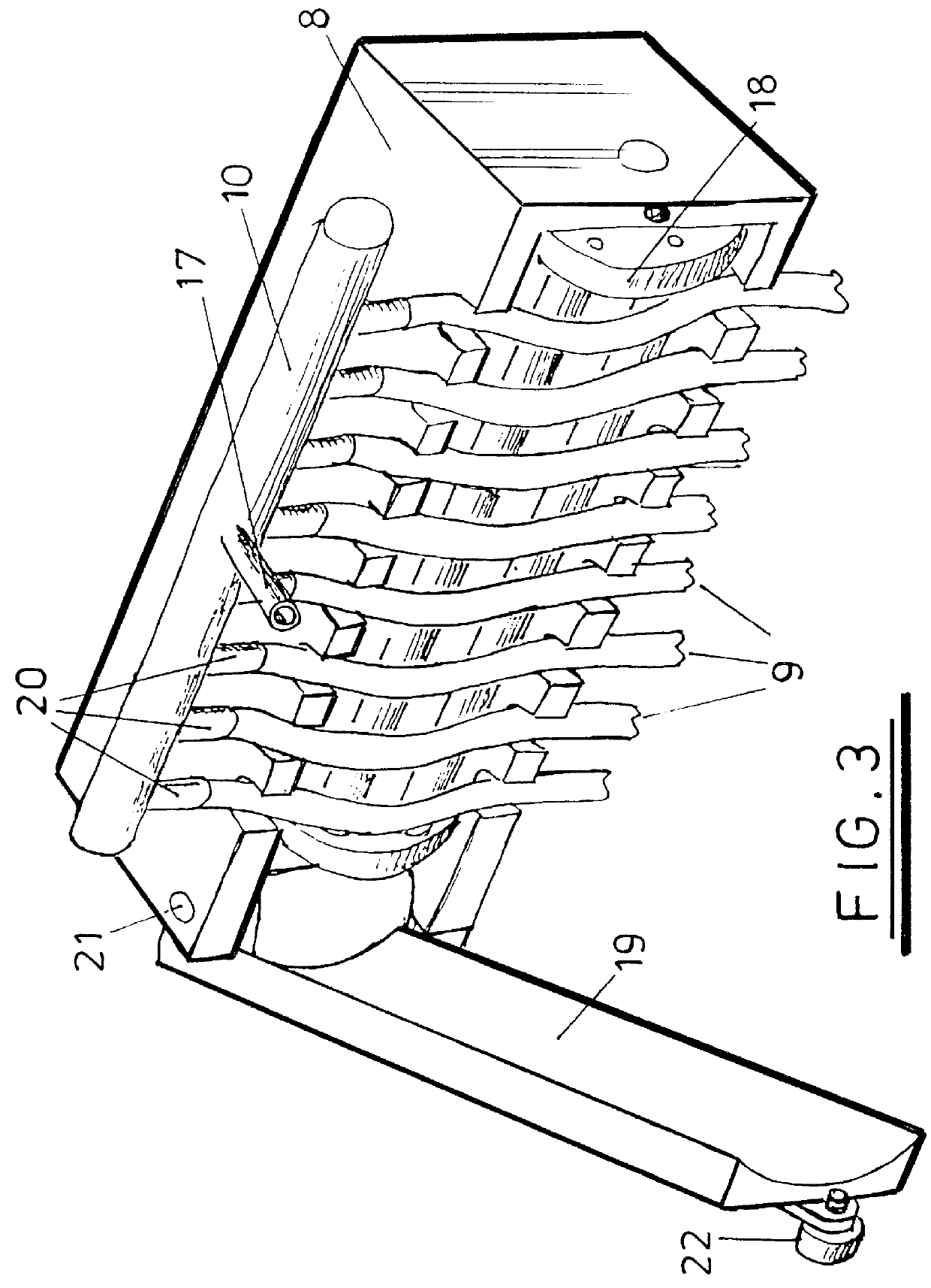
The rotor 3 releasably houses a plurality of roller bottles 6. The front rotor plate 7 provides mounting for a reversible multi-channel peristaltic pump 8, pump tubes 9 and manifold assembly 10. The roller bottles 6 are fitted with dip tube / vent cap assemblies 11. Air vents 12 communicate to atmosphere via microporous filters 13. The dip tubes 14 are extended downwards from the axis of the cap 11 on the interior of the bottle 6 so as to dip into the process fluid 15 when the rotor is in the upright position as shown.

The dip tubes 14 of the cap assemblies 11 are individually connected to the branches 20 of the manifold assembly 10 using flexible pump tub...


PUM

PropertyMeasurementUnit
speedaaaaaaaaaa
pressureaaaaaaaaaa
flexibleaaaaaaaaaa

Abstract

PCT No. PCT / GB95 / 01833 Sec. 371 Date Feb. 12, 1997 Sec. 102(e) Date Feb. 12, 1997 PCT Filed Aug. 2, 1995 PCT Pub. No. WO96 / 05285 PCT Pub. Date Feb. 22, 1996A cell culture apparatus is disclosed. The cell culture apparatus includes a chassis or supporting frame. The cell culture apparatus also includes a rotor releasably housing a plurality of cell culture vessels / roller bottles, the rotor being mounted about a substantially horizontal axis or shaft supported by said frame, with means provided to facilitate rotation of the rotor at a controlled speed. The cell culture apparatus also includes a reversible multi-channel pump or pumps, mounted on and rotating with the rotor. The cell culture apparatus also includes a manifold with one or more sealable external connections and a plurality of connections communicating with the individual channels of the multi-channel pump or pumps, each of the cell culture vessels being equipped with a microporous air vent to atmosphere and a dip tube. The dip tube is fixed with respect to the cell culture vessel and positioned to permit extraction of fluid when the cell culture vessel is stopped in a specific orientation. The dip tube of each vessel is individually connected to one channel of said multi-channel pump or pumps. The arrangement of the parts is such that the assembly comprising the rotor, cell culture vessels, pump, manifold and the connections to the cell culture vessels are rotatable about the horizontal axis. The arrangement also allows fluid to be injected into or extracted from the roller bottles simultaneously via a single external connection, under the influence of the multi-channel pump or pumps.

Description

This invention relates to apparatus for the large scale processing of cell cultures.BACKGROUND TO THE INVENTIONThe rapid growth of biotechnology has led to the need for large scale tissue culture techniques for anchorage dependent cells. Roller bottles are used extensively in the industry for this purpose. Cells are cultured whilst attached to the interior of the roller bottle. Existing roller bottle machines provide for rotation of the bottles to keep the cells bathed in culture medium during culture stages. The processing operations such as innoculation, culture medium supply, or harvesting for example which require the flow of fluids into or out of the roller bottle are carried out manually or by expensive mechanical handling systems such as robots.For large scale production, this process can be awkward, time consuming, and carries the risk of infection of the bottle contents by foreign organisms during handling.In some systems, the need to physically handle the roller bottles is...

Claims


Application Information

Patent Timeline
Patent Type & Authority Patents(United States)
IPC IPC(8): C12M3/04C12M3/02
CPCC12M27/12C12M29/04Y10S435/809
Inventor POWELL, ALEXANDER ROBERT
Owner POWELL BIOLOGICAL MACHINES
Why Eureka
Try Eureka