Cutter with polycrystalline diamond layer and conic section profile

a technology of conic section and diamond layer, which is applied in the direction of drill bits, earthwork drilling and mining, construction, etc., can solve the problem that more wear scars will have a tendency to mov

Inactive Publication Date: 2000-05-30
US SYNTHETIC CORP
View PDF52 Cites 98 Cited by
  • Summary
  • Abstract
  • Description
  • Claims
  • Application Information

AI Technical Summary

Benefits of technology

The invention is a compact-type cutter for use in fixed-cutter rotary drag bits. An example of such a drag bit is depicted in FIG. 1. The cutter is a composite having a polycrystalline diamond cutting surface on a carbide substrate. The polycrystalline diamond forms a layer which covers one face of the cutter and extends into the central portion of the cutter as a ridge-like structure. On the side of the cutter, the ridge-like structure presents a parabolic region of polycrystalline diamond which extends downward from the face of the cutter. The parabolic region of diamond corresponds to the region of the cutter in which a wear scar (or wear flat) would be formed during the drilling operation. By constructing this region of the cutter with a harder material (i.e., diamond rather than carbide), wear on the cutter is reduced and cutting action and lifetime of the cutter are improved. An example of one embodiment of the inventive cutter design is shown in FIGS. 6a-6c.
Another object of the invention is to provide a diamond-carbide interface which does not have stress risers. This is achieved with the use of the modified generally parabolic configuration described herein. The chance of cracks being formed at the diamond-carbide interface is thus reduced.

Problems solved by technology

Similarly, the smaller the back rake angle, the more the wear scar will have a tendency to move toward a parabola because of the effect of cutter taper.

Method used


Image

  • Cutter with polycrystalline diamond layer and conic section profile
  • Cutter with polycrystalline diamond layer and conic section profile
  • Cutter with polycrystalline diamond layer and conic section profile

Examples


example i

Simple Parabolic Cutting Surface

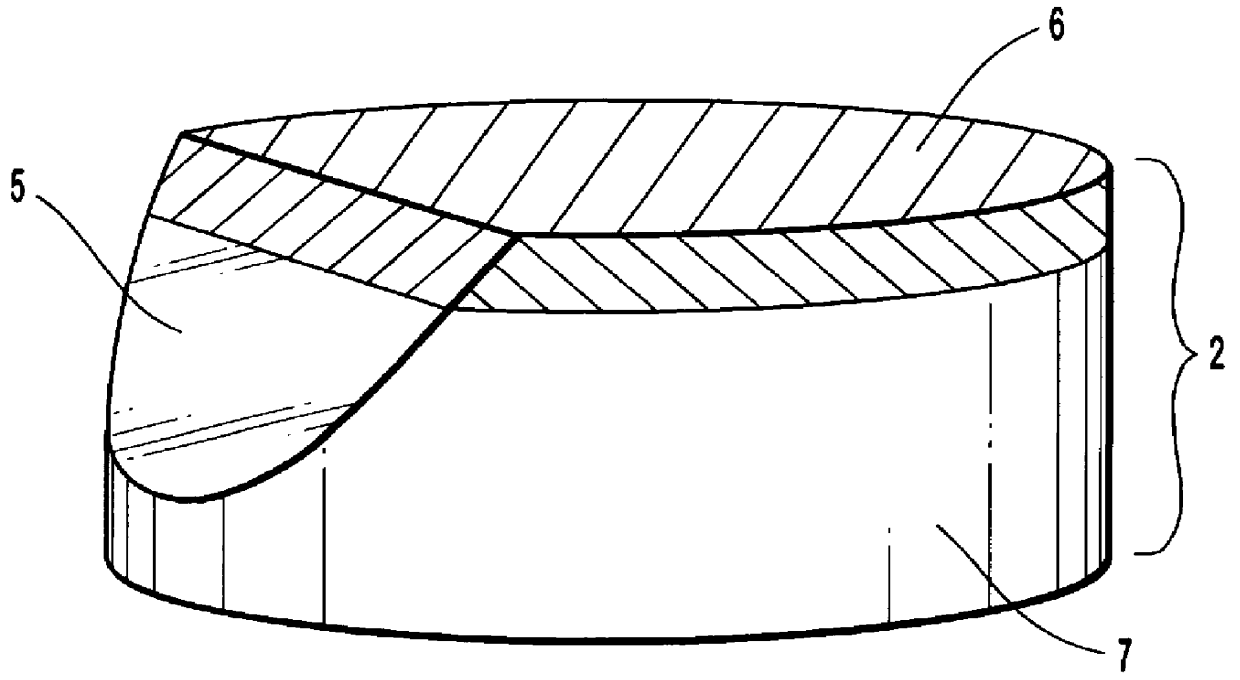
This embodiment of the invention is depicted in FIGS. 6a-6c. The cutter is essentially cylindrical in shape. The inventive cutter has a layer of polycrystalline diamond 6 on a substrate 7. The polycrystalline diamond layer serves as a cutting surface. The cutting surface includes a surface layer which covers on face of the cutter, and, contiguous with the surface layer, a ridge of polycrystalline diamond extending into the substrate. On the side of the cutter, the end of the ridge (seen in cross section) approximates the shape of the wear scar; however, the polycrystalline diamond is not simply a surface feature but extends well into the substrate. This design is based on the theory that the simplest way to prevent a large wear scar from developing is to place a substantial amount of the most wear resistant material (e.g. diamond) in the area of the cutter where the wear scar will develop. Since the wear scar is essentially parabolic in shape, the add...

example ii

Modified Parabolic Cutting Surface

A modification of the simple parabolic design is illustrated below in FIGS. 9a through 9c. The primary focus of this design is to provide as much curved surface as possible to avoid stress concentrations that could cause cracking. This design performs the same functions of the first design. It also illustrates that the curvature of the diamond table may be varied as needed to counter residual stresses which may tear the parabolic region apart. The simple parabolic design has sharp corners 20 (shown in FIG. 6c) where the ridge sides intersect the diamond-carbide interface. This design smoothes that area, and cannot be modeled as a simple parabola. The cross-section shapes shown in FIGS. 7a through 7e can also be modified by the addition of a curved interface region, as shown in FIGS. 7f through 7j.

The same method is used for manufacturing the modified parabolic cutter as is used for manufacturing the simple parabolic cutter.

As shown in FIGS. 6b and 9...


PUM


Abstract

Polycrystalline diamond cutter (PDC) designs which substantially improve the penetration rate of fixed cutter drill bits while simultaneously reducing the wear on the bit during drilling operations are disclosed. The designs are based upon the observation that: 1) the wear pattern of a PDC is roughly a conic section and is parallel to bit rotation, and 2) the cutting surface is perpendicular to the rotation of the bit. The inventive PDC designs provide cutting action both perpendicular and parallel to the direction of bit rotation.

Description

I. BACKGROUND OF THE INVENTIONA. Field of the InventionThis invention relates to the design of cutters used in fixed cutter drill bits such as are used for drilling holes for blasting, and oil and gas exploration and production. In particular, this invention relates to cutters for use on rotary drag bits which are configured to maximize wear resistance and to enhance drill bit performance.B. The Background ArtIt is known in the prior art to construct drill bits for drilling holes in rock formations by affixing a plurality of discrete cutting elements made of a superhard material (typically diamond) to a substrate of some other material, such as tungsten carbide. In the past, chips of diamond set in the surface of a drill bit, as disclosed by Havlick (U.S. Pat. No. 2,264,440) have been used. More recently it has become common for drill bits to include cutting elements which are composites of a substrate material (e.g. tungsten carbide) and a superhard material (e.g. polycrystalline d...

Claims


Application Information

Patent Timeline
Patent Type & Authority Patents(United States)
IPC IPC(8): E21B10/46E21B10/56E21B10/567E21B10/573
CPCE21B10/5735E21B10/567E21B10/5673
Inventor JUREWICZ, STEPHEN R.
Owner US SYNTHETIC CORP
Why Eureka
Try Eureka