Machine tool having a gantry and a vertical spindle

a technology of gantry and machine tool, which is applied in the direction of large fixed members, veneer manufacturing, chemical debarking, etc., can solve the problems of increasing the weight of the cursor-carrier, affecting the accuracy of machining, and mechanical deformation, so as to facilitate the remedy of the cursor-carrier deformation

Inactive Publication Date: 2000-05-30
HELIS
View PDF14 Cites 46 Cited by
  • Summary
  • Abstract
  • Description
  • Claims
  • Application Information

AI Technical Summary

Benefits of technology

The object of the invention is to propose a novel structure for the gantry and the means for mounting the cursor on the gantry, making it easy to remedy deformation of the cursor-carrier without excessively increasing weight.

Problems solved by technology

That U-shaped configuration of the cursor-carrier gives rise to mechanical deformation which is harmful for machining accuracy, particularly when the distance between the flanges is designed to make it possible to move the spindle a long way along the X axis without moving the gantry.
To remedy that problem, it is necessary to increase the dimensions of the cursor-carrier, thereby increasing its weight, which gives rise to an increase in the inertia of the moving parts, and thus to a decrease in displacement speed.

Method used


Image

  • Machine tool having a gantry and a vertical spindle
  • Machine tool having a gantry and a vertical spindle

Examples


Embodiment Construction

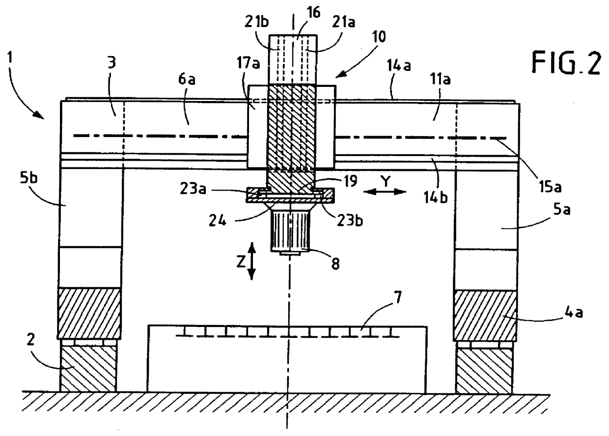
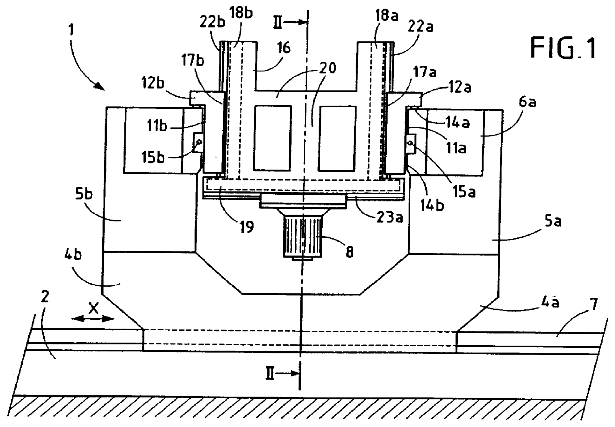
In the drawing, reference 1 designates a milling machine having a vertical spindle and a moving gantry. The machine comprises, in conventional manner, a rigid bench 2 on which a gantry 3 is mounted to move along an X axis. The gantry has two vertical uprights 4a, 4b, each terminated at its top by two cradles 5a, 5b that are spaced apart in the X axis direction. The two parallel beams 6a, 6b fixed respectively on the front cradles 5a of the two uprights 4a, 4b, and on the rear cradles 5b of said uprights. The beams 6a, 6b define a transverse Y axis that is perpendicular to the X axis, and together they constitute the top cross-member of the gantry 3. A traditional drive system enables the gantry 3 to be displaced. Reference 7 designates a support table for the part that is to be machined. Reference 8 designates a tool-carrying spindle capable of rotating about a vertical Z axis and mounted on the beams 6a and 6b by mounting means 10 in such a manner that the tool-carrying spindle 8 c...


PUM

PropertyMeasurementUnit
mechanical deformationaaaaaaaaaa
weightaaaaaaaaaa
displacement speedaaaaaaaaaa

Abstract

The invention relates to a machine tool having a gantry that is movable along an X axis and having a vertical spindle supported by the cross-member of the gantry. The cross-member comprises two beams that are spaced apart in the X axis direction and that have facing inside faces. Two carriages are mounted to slide on said facing faces, on opposite sides of a vertically movable cursor-carrier. The tool-carrier spindle is carried by a cursor mounted to slide on the bottom face of the cursor-carrier and movable along the X axis. Movements of the carriages, of the cursor-carrier and of cursor are under numerical control. The tool-carrier spindle can move in the X axis direction without it being necessary to move the gantry.

Description

The present invention relates to large capacity machine tools and in particular to milling machines having vertical spindles and moving gantries.More precisely, the invention relates to a machine tool comprising a rigid bench, a gantry having two uprights interconnected by a top cross-member having two faces spaced apart in the direction of an X axis, means for moving the gantry on said bench along the X axis, two carriages disposed respectively on said spaced-apart faces of the cross-member and movable along a transverse Y axis, a cursor-carrier supported by said carriages and movable along a vertical Z axis, a cursor mounted on said cursor-carrier and movable along the X axis, a tool-carrier spindle carried by said cursor and capable of rotating about the Z axis, and a numerical control system for controlling synchronized movements of the two carriages along the Y axis, movement of said cursor-carrier along the Z axis, and movement of said cursor relative to said cursor-carrier al...

Claims


Application Information

Patent Timeline
Patent Type & Authority Patents(United States)
IPC IPC(8): B23Q1/00B23Q1/01
CPCB23Q1/012Y10T29/53539Y10T409/307728B23Q1/017
Inventor LINE, HENRI
Owner HELIS
Why Eureka
Try Eureka