

Non-contact IC card with monitor for source power
a source power, non-contact technology, applied in the field of non-contact ic cards, can solve the problems of data storage in memory section 106 being destroyed, the voltage supplied to each section declines, and the operation of each section becomes unstabl
- Summary
- Abstract
- Description
- Claims
- Application Information
AI Technical Summary
Benefits of technology
Problems solved by technology
Method used
Image


Examples
first embodiment
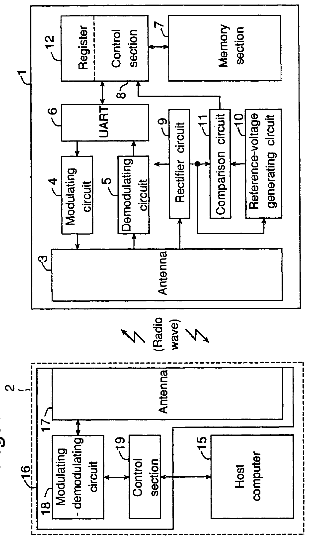
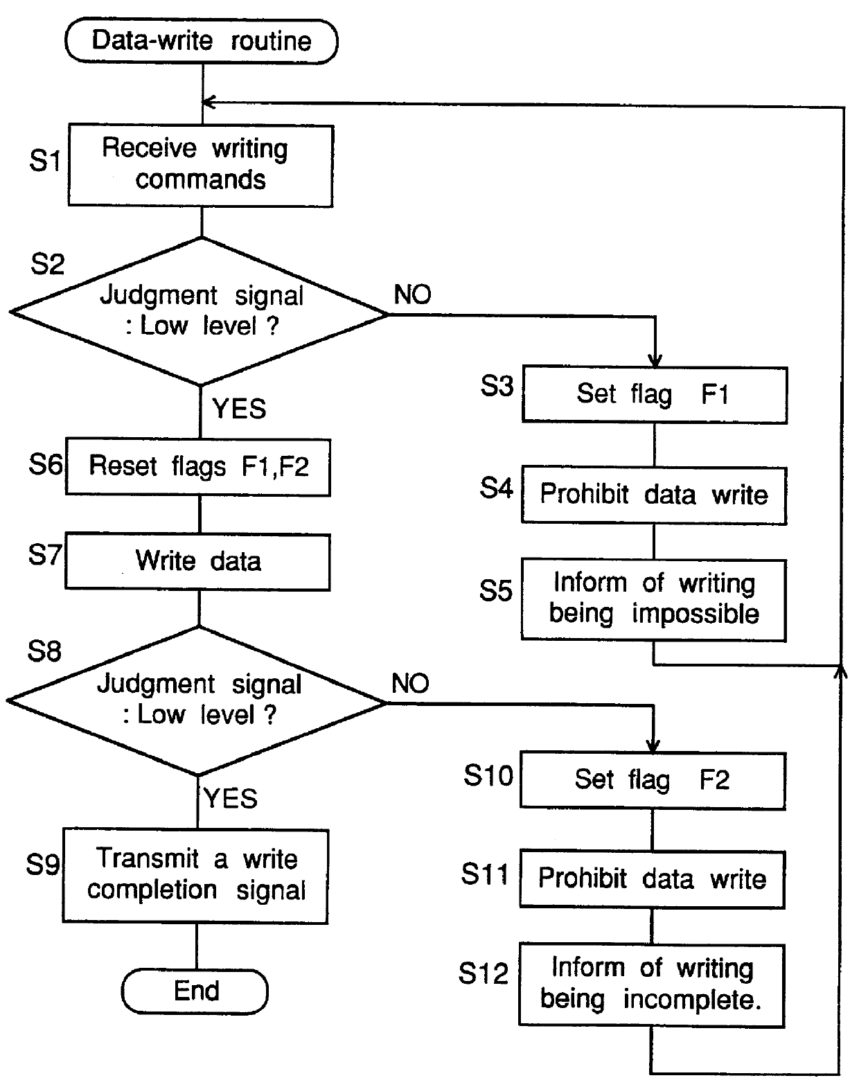
As described above, the non-contact type IC card of the first embodiment in accordance with the present invention monitors changes in the source voltage output from rectifier circuit 9, due to changes in the electric field strength of the received radio wave. The IC card prohibits the writing of data into memory section 7 and transmits a signal that indicates the writing of data is impossible, into host system apparatus 2, if the source voltage becomes less than the reference voltage a. Consequently, the IC card can prevent the writing of data from becoming incomplete caused by changes in the electric field strength of the received radio wave, so that the reliability of the writing of data can be improved.
second embodiment
In the first embodiment described above, the voltage of the power output from the rectifier circuit 9 has been supplied to each section as source voltage. In a second embodiment described in the following, the voltage of the power output from the rectifier circuit 9 is regulated so as not to exceed a constant value and supplied to each section as source voltage.
FIG. 4 is a block diagram illustrating a non-contact type IC card in the second embodiment. FIG. 4 differs from FIG. 1 in that the IC card has additionally a regulator circuit 21 that keeps constant the voltage of the power output from rectifier circuit 9, to supply the regulated power to each section. Further, the reference-voltage generating circuit 10 is replaced with a reference-current generating circuit 22. The comparison circuit 11 is altered into a comparison circuit 23 that compares the source current input from regulator circuit 21 with the reference current input from reference-current generating circuit 22. With t...
third embodiment
In the first and second embodiments described above, if the source voltage declines during the time when data is written into memory section 7, then the writing of data is prohibited before it is completed. Therefore, at that time, the writing of data is terminated incompletely. Therefore, in the third embodiment described in the following, the IC card has an auxiliary power supply formed of a capacitor so that the writing of data should be completed, even if the source voltage declines so much as the writing cannot be continued during the time when data is written.
FIG. 6 is a block diagram illustrating a non-contact type IC card in the third embodiment. FIG. 6 differs from FIG. 1 in that the IC card has additionally a capacitor 31. Also, if control circuit 8 receives a judgment signal of HIGH level from comparison circuit 11 because the source voltage input from rectifier circuit 9 becomes less than the reference voltage a during the writing of data, the control circuit 8 resets th...
PUM
 Abstract
Description
Claims
Application Information