E-1 air dryer liquid separator with baffle

a technology of air dryer and liquid separator, which is applied in the direction of liquid degasification, auxillary pretreatment, separation process, etc., can solve the problems of limited amount of moisture, inability to remove a certain amount, and inability to completely trouble-free operation, etc., and achieves the effect of low cost and simple removal

Inactive Publication Date: 2000-06-06
WESTINGHOUSE AIR BRAKE CO
View PDF5 Cites 119 Cited by
  • Summary
  • Abstract
  • Description
  • Claims
  • Application Information

AI Technical Summary

Benefits of technology

A further object of this invention is to provide an improved centrifugal separator for removing liquid or moisture from a gas which works adequately even though the inlet gas may be under significant pressure.
It is still another object of this invention to provide a separator for removing liquid or moisture from a compressed gas which permits periodic draining of the separated liquid without causing turbulence within the separator of such magnitude as to redissolve any significant portion of the separated moisture back into the compressed gas.
An even further object of this invention is to provide a simple and low cost separator for removing water from compressed air as may be advantageously incorpor

Problems solved by technology

Another disadvantage of the single tower air drying system is that it is only capable of removing a certain, limited amount of moisture during the purge mode.
Because the volume of unpurified air flowing into the system to be dried vastly exceeds the volume of purified air used to purge the desiccant media, the desiccant media never adequately exsiccates during operation of the single tower system.
While the twin tower system has a greatly increased water removing capacity, it is still not as great as would be desired for completely trouble free operation.
Most such systems, however, require the use of moving parts or coalescing filters which would significantly increase maintenance costs or unduly complicate the system.
Indeed, centrifugal separators have been utilized in twin tower air drying systems, but with only a moderate degree of success.
In a compressed air system where the air is conveyed under a considerable pressure, the high pressure of the compressed air causes a very significant turbulence within the centrifugal separator when the drain is opened to permit the water to be drained therefrom.
This turbulence caus

Method used


Image

  • E-1 air dryer liquid separator with baffle
  • E-1 air dryer liquid separator with baffle
  • E-1 air dryer liquid separator with baffle

Examples


Embodiment Construction

, particularly, when such description is taken in conjunction with the attached drawing figures and the appended claims.

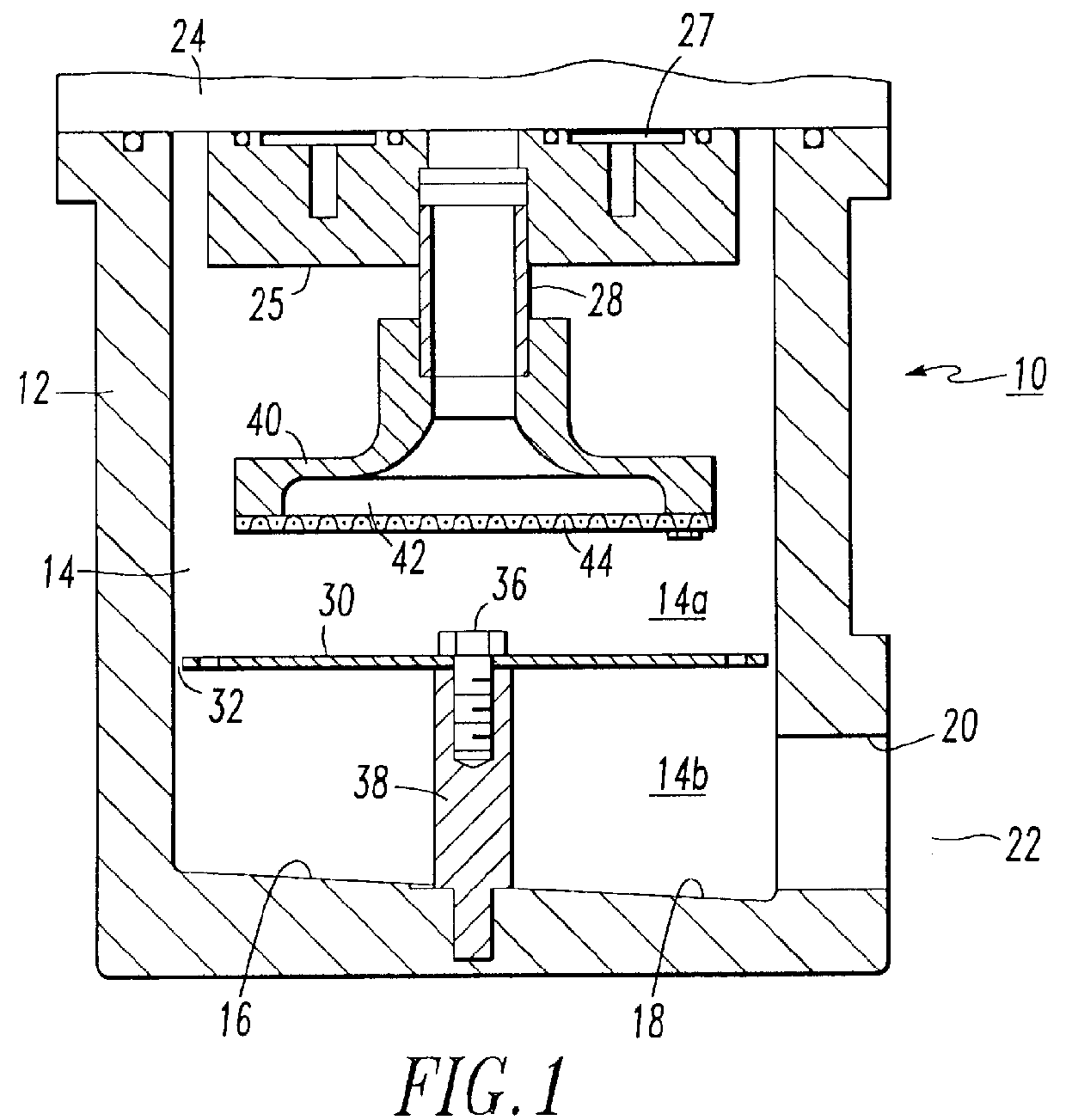
FIG. 1 is a cross-sectional side view of a centrifugal separator according to a presently preferred embodiment of this invention wherein the separator has a cylindrical chamber.

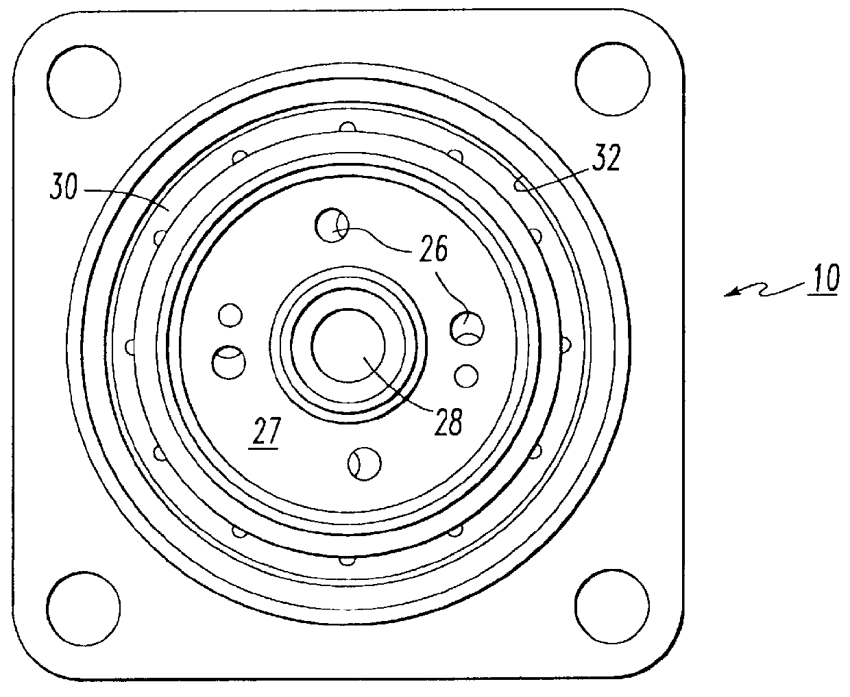
FIG. 2 is a top view of the centrifugal separator shown in FIG. 1 with the cover removed so that the interior of the chamber can be viewed.

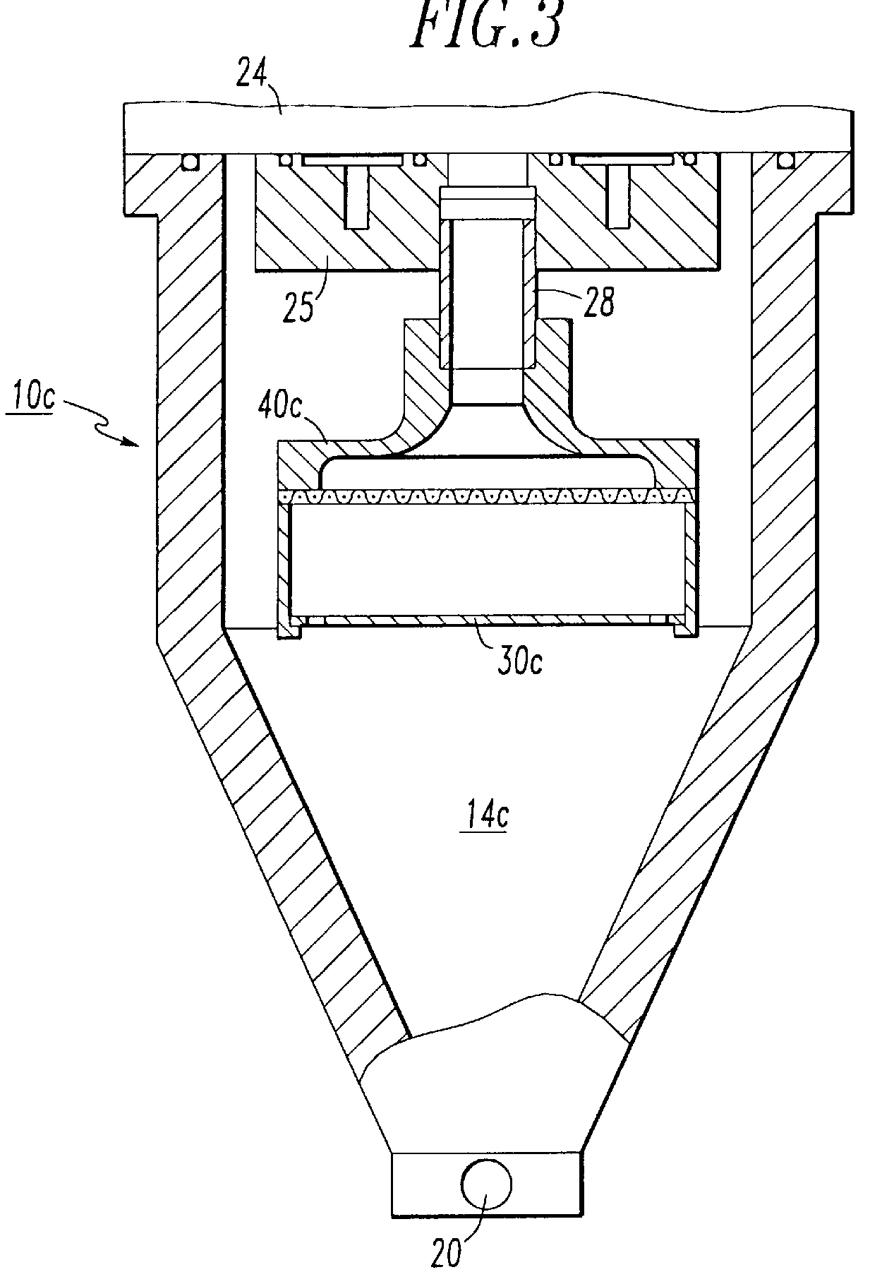
FIG. 3 is a cross-sectional side view substantially like that of FIG. 1 but showing the separator as having a conical chamber with the baffel suspended from above.

FIG. 4 is an exploded view of the centrifugal separator shown in FIGS. 1-2.

FIG. 5 is a cross-sectional view of a twin tower air cleaning system incorporating the centrifugal separator as illustrated in FIGS. 1-2 and 4, with the bottom of the centrifugal separator casting functioning as the cover for the centrifugal separator.

FIG. 6 is an isometric view of the inlet means for admitting the moist,...


PUM

PropertyMeasurementUnit
Diameteraaaaaaaaaa

Abstract

In a centrifugal separator for separating a liquid from a compressed gas, a baffle is provided to separate the centrifugal chamber into an upper sub-chamber and a lower sub-chamber but does not contact the walls of the chamber thereby being insufficient to prevent downward flow of separated liquid along the interior wall of the two sub-chambers, and insufficient to prevent flow of compressed gas from one sub-chamber to the other sub-chamber, the baffle nevertheless being sufficient to prevent turbulent gas flow in the lower sub-chamber when collected liquid is drained therefrom.

Description

The invention taught in this patent application is closely related to the inventions taught in U.S. Pat. Nos. 5,423,129, 5,604,991 and 5,685,896; and is further closely related to the following copending patent applications: "Control Valve With Axial Sealing", Ser. No. 08 / 978,551, now U.S. Pat. No. 6,000,432; "Shuttle Mechanism For Twin Tower Air Dryer System", Ser. No. 08 / 979,198, now U.S. Pat. No. 5,901,459; "Purge Tube With Flapper Valve For Desiccant Containing Air Drier", Ser. No. 08 / 979,197 now U.S. Pat. No. 5,930,910; "E-1 Twin Tower Air Dryer For An Air Compressor Unit", Ser. No. 08 / 979,649 now U.S. Pat. No. 5,901,464; all of which are being filed concurrently herewith. All of the above-referenced patents and patent applications are assigned to the assignee of this invention. Additionally, the teachings of each of these issued and co-pending patent applications is incorporated herein by reference thereto.The present invention generally relates to a new and improved centrifug...

Claims


Application Information

Patent Timeline
IPC IPC(8): B01D45/16B01D45/12B01D53/26B04C5/00B04C5/103
CPCB01D45/16B04C5/103B01D53/261Y10S55/17
Inventor TRAPP, SCOTT M.KAZAKIS, MICHAEL V.CASTLE, T. KEVIN
Owner WESTINGHOUSE AIR BRAKE CO
Why Eureka
Try Eureka