Check patentability & draft patents in minutes with Patsnap Eureka AI!

Electrolytic method for purifying gases

a technology of purifying gas and electrolysis, which is applied in the direction of separation process, dispersed particle separation, chemistry apparatus and processes, etc., can solve the problems of high residual content of impurities in the purified gas, the necessity of using certain chemicals, and the frequent appearance of waste water disposal problems

Inactive Publication Date: 2000-06-06
DEGUSSA AG
View PDF7 Cites 13 Cited by
  • Summary
  • Abstract
  • Description
  • Claims
  • Application Information

AI Technical Summary

Benefits of technology

are achieved by a method for the electrolytic removal of an electrochemically convertible impurity from gases in which the gas to be purified and a liquid electrolyte are conducted in cocurrent flow or countercurrent flow over a fixed-bed electrode of an electrolysis cell and in which the impurity is converted upon an effective cell voltage. The method of the invention features using an electrolysis cell which comprises a counter...

Problems solved by technology

A disadvantage is the necessity of having to use certain chemicals.
As a result, a waste-water disposal problem frequently arises on account of the reaction product formed in the wash solution and stemming from a waste gas problem.
A disadvantage of the method of Kreysa et al. is the high residual content of impurities in the purified gas.
A disadvantage of the previously known method is the fact that the apparatus comprising an electrolysis cell requires two liquid circuits, namely a catholyte circuit and an anolyte circuit, as a result of which the device is rendered complicated and trouble-prone.

Method used


Image

  • Electrolytic method for purifying gases
  • Electrolytic method for purifying gases

Examples


example 1

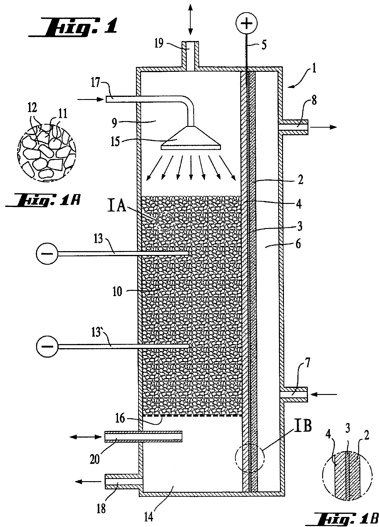
Depletion experiments with a waste gas containing 0.1% by volume Cl.sub.2 were carried out with the cell shown in FIG. 1 with a gas diffusion anode consisting of a graphite support with a Pt coating. In order to avoid a short circuit a microporous membrane was placed between the gas diffusion electrode and the graphite bed.

In order to achieve a depletion of approximately 100% at maximum gas density care must be taken to obtain a good contacting of the gas diffusion electrode. A uniform and sufficiently large number of electric contacts on the gas diffusion electrode have a favorable effect on the cell voltage and on the achievable gas throughput. The best result is obtained if the anode compartment is filled with graphite spheres, thus producing an optimum contact to the gas diffusion anode using an anode end plate (see table 1).

The pressure difference between the anode compartment and the cathode compartment must not be more than 0.5 mbar with an uncoated gas diffusion electrode.

example 2

A gas diffusion electrode coated with NAFION.RTM. as cation exchange membrane is inserted into the cell shown in FIG. 1. The gas diffusion electrode was produced by pressing together platinized black and polytetrafluoroethylene. A larger pressure difference than 0.5 mbar is possible between the anode compartment and the cathode compartment on account of the 40-50 .mu.m thick coating with the Nafion.RTM. membrane, nearly not permeable for gases.


PUM

PropertyMeasurementUnit
Flow rateaaaaaaaaaa
Electrical conductoraaaaaaaaaa
Electric potential / voltageaaaaaaaaaa

Abstract

An electrolysis cell with a fixed-bed electrode and its use for the purification of waste gases. The electrolysis cell includes a fixed-bed electrode, a counterelectrode which is separated from it and designed as a gas diffusion electrode, devices for the supply and flow-off of an electrolyte as well as for the inlet and outlet of the gas to be purified and a space associated with the counterelectrode with devices for the supply and the removal of a gas. In order to purify gas the fixed-bed electrode is operated as a trickle bed and the gas to be purified flows in cocurrent or countercurrent flow to the electrolyte. In reductive purification hydrogen is supplied to the gas diffusion electrode and in oxidative purification oxygen is used.

Description

INTRODUCTION AND BACKGROUNDThe present invention relates to an electrolysis cell for the electrolytic removal of an electrochemically convertible impurity from gases as well as to a method of purifying gases using this electrolysis cell.Gaseous pollutants or impurities in gases such as e.g. Cl.sub.2, SO.sub.2, NO.sub.x and mercaptans can be removed by a wet-chemical wash with a wash solution. Absorption apparatuses such as e.g. packed columns are used for such a purification. In order to obtain a good purifying action the absorbed gaseous component must be rapidly converted. A disadvantage is the necessity of having to use certain chemicals. As a result, a waste-water disposal problem frequently arises on account of the reaction product formed in the wash solution and stemming from a waste gas problem.Methods are even known for the electrochemical purification of waste gases. In the so-called "outer-cell" methods the gaseous component of a waste gas to be stripped is first absorbed ...

Claims


Application Information

Patent Timeline
IPC IPC(8): B01D53/32C02F1/461C02F1/467
CPCB01D53/326C02F1/467C02F1/46114C02F1/46109
Inventor ENGEL, DIETERLEHMANN, THOMASTROLL, HARALD
Owner DEGUSSA AG
Features
  • R&D
  • Intellectual Property
  • Life Sciences
  • Materials
  • Tech Scout
  • Unparalleled Data Quality
  • Higher Quality Content
  • 60% Fewer Hallucinations
Learn More