Microwave antenna transmission device having a stripline to waveguide transition via a slot coupling

a transmission device and microwave antenna technology, applied in slot antennas, antennas, electrical devices, etc., can solve the problems of low efficiency, high cost and relatively complex construction of adaptation chambers, and the effect of reducing the efficiency of reflection

Inactive Publication Date: 2000-06-27
TELEFON AB LM ERICSSON (PUBL)
View PDF10 Cites 56 Cited by
  • Summary
  • Abstract
  • Description
  • Claims
  • Application Information

AI Technical Summary

Benefits of technology

Another object of the invention is the possibility to achieve a device for power transmission in microwave antennas, preferably group antennas, where the antenna elements are achieved by means of cavity waveguides, in which high efficiency may be combined with low complexity, moderate demands on mechanical precision and small demands on space, especially depthwise.
One advantage of the present invention is that a device for power transmission of electromagnetic microwaves between a first transmission conduction device and a second transmission conduction device is achieved in which high efficiency may be combined with good bandwidth and small demands on space.
Another advantage of the present invention is the possibility to achieve a device for power transmission of electromagnetic microwaves to and / or from group antennas, which is adapted to mobile applications where strict space requirements are required.
A further advantage of the present invention is the possibility to achieve a device for power transmission of electromagnetic microwaves between a first transmission conductor device and a second transmission conductor device, in which the mutual relationship of all elements demands high mechanical precision, may be realized in one and the same building element, thus all these demands may be fulfilled without difficulty.
Yet another advantage of the present invention is the possibility to achieve a device for power transmission for microwave group antennas, in which the antenna elements are achieved by means of a cavity waveguide, wherein one and the same transmission conductor device, e.g. being a strip-line card, may be used for power transmission to and from several of the cavity waveguides comprised in the antenna.

Problems solved by technology

The construction described in U.S. Pat. No. 5,028,891 having adaptation chambers is, however, expensive and relatively complex.
The shown construction also demands relatively much space depthwise, which presents a substantial drawback in antenna constructions where the available space often constitutes a limiting factor.
Further, this construction is sensitive to a possible displacement of the aperture in relation to the slot in the earth plane.
If the slot is smaller than the aperture, problems arise with reflections giving less efficiency.
It has earlier been a problem to fulfil these requirements.

Method used


Image

  • Microwave antenna transmission device having a stripline to waveguide transition via a slot coupling
  • Microwave antenna transmission device having a stripline to waveguide transition via a slot coupling
  • Microwave antenna transmission device having a stripline to waveguide transition via a slot coupling

Examples


Embodiment Construction

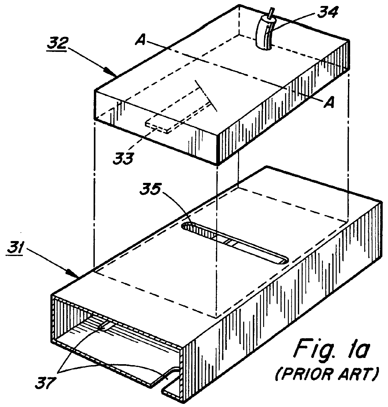
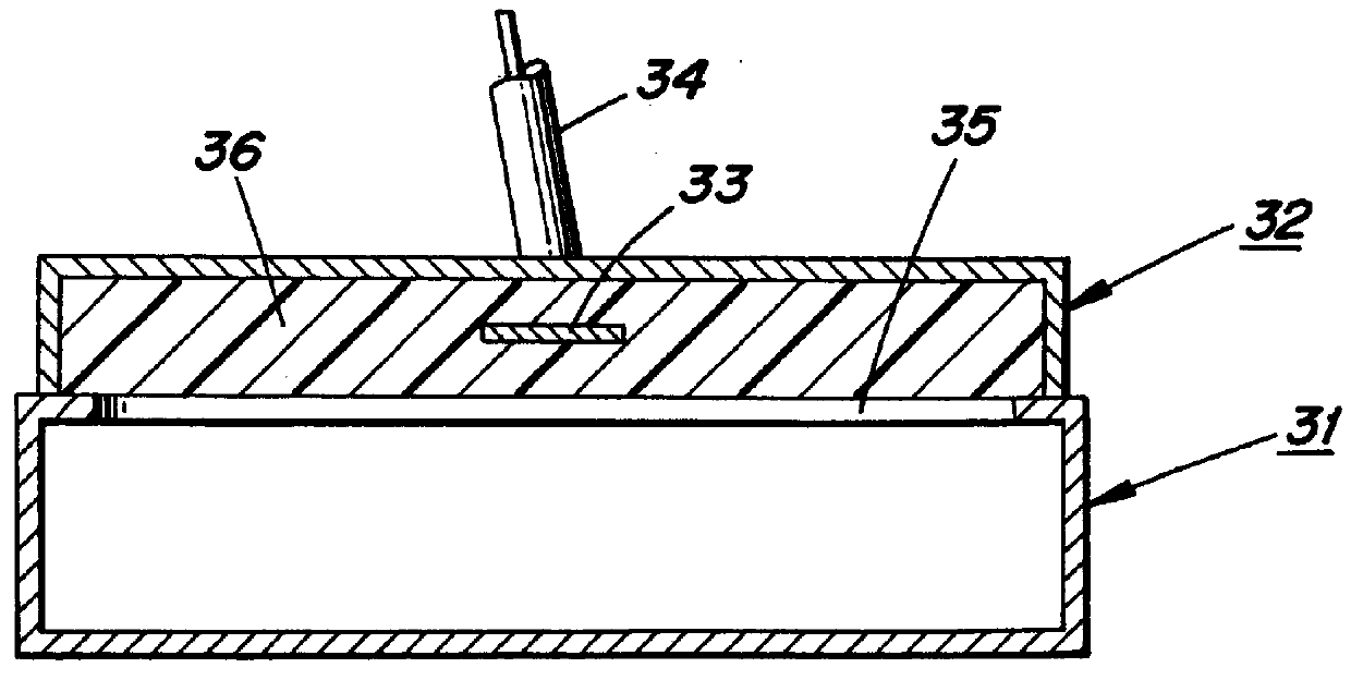
FIG. 1 a shows a cavity waveguide for microwaves as described in U.S. Pat. No. 5,028,891. The cavity waveguide designated 31 is formed of electrically conduction material and exhibits a rectangular cross-section. The cavity waveguide designated 31 supports an adaptation chamber 32 which is coupled to a coaxial conductor 34 having a rotationally symmetric cross-section. The cavity waveguide 31 has on its front side a set of slots 37, through which microwave energy may radiate to the environment. The adaptation chamber 32 is built around a dielectric substrate 36 (See FIG. 1b). This substrate is on five of its six sides surrounded by electrically conducting walls. The sixth side of the substrate 36 abuts the side of the cavity waveguide 31 which is opposite to the side having said set of slots 37. Centrally in the substrate a central conductor 33 arranged in the longitudinal direction of the cavity waveguide. The wall of the cavity waveguide abutting the adap-tation chamber 32 is prov...


PUM


Abstract

A device for the power transmission of microwaves between a strip-line and a number of parallel cavity waveguides arranged in a group antenna. The strip-line includes H-shaped slots. These slots are centered with respect to a central conductor. Opposite each of the slots, a corresponding slot is arranged through the wall of the cavity waveguide. Electrically conducting seals are arranged to follow immediately outside the contours of the slots. The strip-line is fixedly fastened to the seals and the ridge waveguide, whereby good electrical coupling is achieved. Simultaneously, small cavities are formed between the slots. These cavities have a leveling effect such that the demands on mechanical precision is appreciably lowered, such that the tolerance to placement of the slots opposite to each other is increased substantially as compared to the case of the waveguides directly abutting the strip-line.

Description

The invention concerns devices for power transmission between two transmission conductor devices for electromagnetic microwaves, such as a cavity waveguide and a strip-line, via radiation slots. The invention also concerns a microwave antenna coupled by means of such devices.BACKGROUND AND PRIOR ARTGroup antennas for microwaves comprising a desired number of parallel cavity waveguides are known. The cavity waveguides are thereby placed adjacent to each other and on the front sides of the cavity waveguides, a great number of short slots are arranged one after the other, through which microwave energy is emitted to and / or is taken up from the surroundings. The slots are normally evenly spaced along the cavity waveguides. The cavity waveguides may according to a suitable point of view be looked upon as resonance chambers, from which microwaves may be emitted through said slots.In U.S. Pat. No. 5,028,891 an antenna of this type is described, in which the cavity waveguides, which prefera...

Claims


Application Information

Patent Timeline
Patent Type & Authority Patents(United States)
IPC IPC(8): H01P5/10H01P5/107
CPCH01P5/107
Inventor JOSEFSSON, LARS GUSTAFERIKSSON, MATS GUNNAR H.ANG.KANMALM, LARS BERTILBERGENDAHL, JAN MICHAEL
Owner TELEFON AB LM ERICSSON (PUBL)
Why Eureka
Try Eureka