Device for applying wetting agent to a cylinder of a rotary printing machine

a technology of rotary printing machine and wetting agent, which is applied in the direction of rotary lithographic machine, office printing, printing, etc., can solve the problems of large production volume, fluctuation in the quality of printed images, and visible water marks on printed images

Inactive Publication Date: 2000-07-18
M A N ROLAND DRUCKMASCHINEN AG
View PDF16 Cites 8 Cited by
  • Summary
  • Abstract
  • Description
  • Claims
  • Application Information

AI Technical Summary

Problems solved by technology

However, a problem with this device is that the spray effects of adjacently arranged nozzles overlap, leading to fluctuations in the quality of the printed image.
In addition, the drops produced are relatively large which leaves visible water marks on the printed image, despite being split and distributed in the wetting mechanism.
The results are impaired quality and spoilage.
The requirement of pressurized air and its associated control makes this device and its operation expensive.
In addition, the use of pressurized air causes a sometimes hazardous wetting agent mist to emerge into the surrounding environment.
The thus created mist then reaches the pl

Method used


Image

  • Device for applying wetting agent to a cylinder of a rotary printing machine
  • Device for applying wetting agent to a cylinder of a rotary printing machine
  • Device for applying wetting agent to a cylinder of a rotary printing machine

Examples


Embodiment Construction

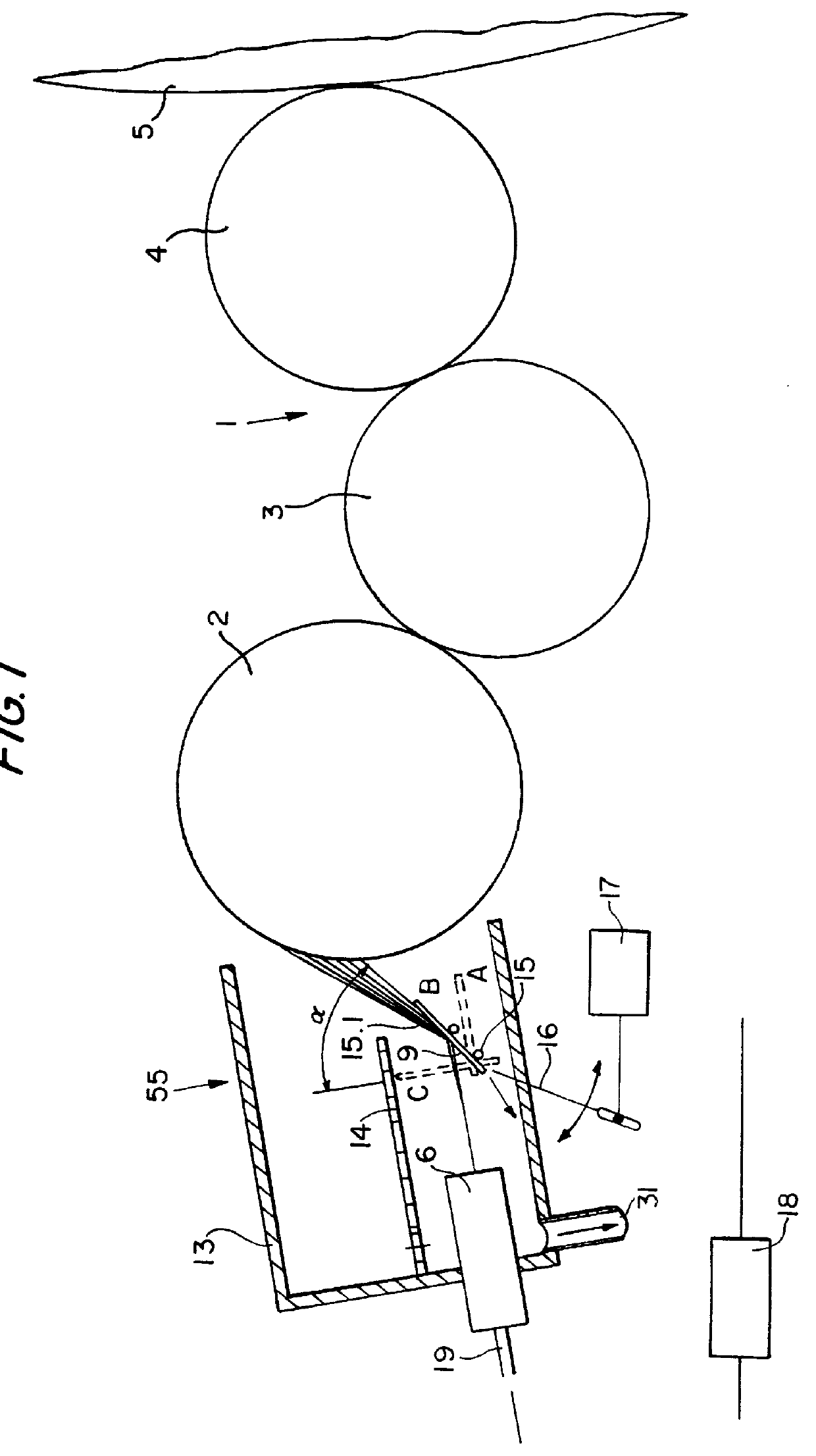
FIG. 1 shows a device 55 for applying a wetting agent according to the present invention arranged on a cylinder of a wetting mechanism 1 of a rotary printing machine. In FIG. 1, the device 55 is positioned on a distributor cylinder 2, which is followed by a transfer roller 3 and a wetting agent application roller 4, which contacts the form cylinder 5. Depending on particular arrangement of the wetting mechanism 1, the device 55 for applying a wetting agent may, for example, be located on the transfer roller 3 if the distributor cylinder 2 is omitted, or on the wetting agent application roller 4 if the distributor roller 2 and transfer roller 3 are omitted. The wetting mechanism 1 may also have a different structure.

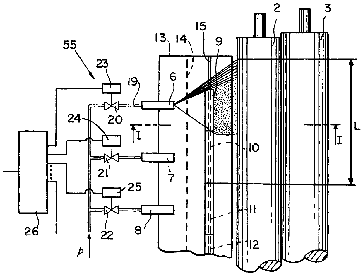
Referring also to FIG. 2, the device 55 contains nozzles 6, 7 and 8 arranged along the distributor cylinder 2 to be moistened. To attain good distribution of the wetting agent along the axial direction of the distributor cylinder 2, the nozzles 6 to 8 are preferably embod...


PUM


Abstract

An economical device for applying a wetting agent in the form of small droplets to a cylinder includes nozzles which are supplied continuously with pressurized wetting agent arranged along the cylinder. An adjustment element in the spray area of the nozzles doses the wetting agent application that is maximally one printed page wide.

Description

1. Field of the InventionThe present invention relates to a device for applying wetting agent to a cylinder of a rotary printing machine.2. Description of the Related ArtA prior art device for applying a wetting agent to a cylinder in a printing machine is disclosed in German reference DE 29 31 579 C2. In that reference, a wetting agent is applied to a cylinder of a wetting mechanism in a rotary printing machine by nozzles. The nozzles are arranged along the cylinder. To control the dispensing of emerging water relative to the machine speed, an orifice plate having a controllable opening is placed over the width of the printing form. However, a problem with this device is that the spray effects of adjacently arranged nozzles overlap, leading to fluctuations in the quality of the printed image. In addition, the drops produced are relatively large which leaves visible water marks on the printed image, despite being split and distributed in the wetting mechanism. The results are impair...

Claims


Application Information

Patent Timeline
IPC IPC(8): B41F7/30B41F7/00
CPCB41F7/30
Inventor REGELE, STEPHANBATKE, MANFRED
Owner M A N ROLAND DRUCKMASCHINEN AG
Why Eureka
Try Eureka