Piston pump

a pump and piston technology, applied in the field of piston pumps, can solve the problems of inaccurate pressure point upon actuation of the vehicle brake system, increased production cost of pressure fluid reservoirs, and poor pump efficiency, and achieve the effects of improving pump efficiency, improving pump efficiency, and improving pump efficiency

Inactive Publication Date: 2000-07-25
ROBERT BOSCH GMBH
View PDF11 Cites 42 Cited by
  • Summary
  • Abstract
  • Description
  • Claims
  • Application Information

AI Technical Summary

Benefits of technology

In the piston pump of the invention as defined by the main claim, a fluid reservoir with a storage volume is provided inside the piston pump itself. As a result, the storage volume is available to the piston pump immediately within an aspiration region of the piston pump itself and thus over the shortest possible path, with at most one inlet valve as the sole throttle restriction, between the storage volume and...

Problems solved by technology

A problem in the known piston pumps is their aspiration performance, especially at low temperatures and with fluid to be pumped that is consequently viscous.
However, the known vehicle brake system has the disadvantage that the pressure fluid reservoir entails ...

Method used


Image

  • Piston pump
  • Piston pump

Examples


Embodiment Construction

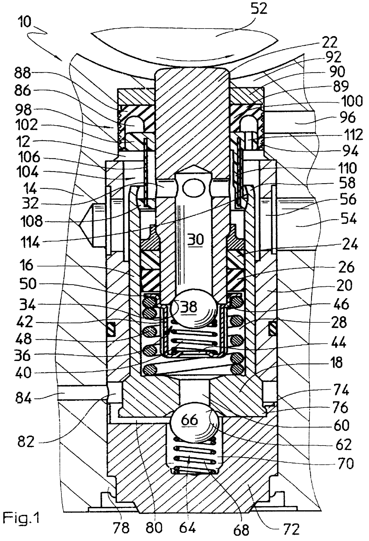
The piston pump of the invention, shown in FIG. 1 and identified overall by reference numeral 10, is inserted into a pump bore 12, which is provided in the form of a stepped, continuous bore in a hydraulic block that forms a pump housing 14. The hydraulic block, of which FIG. 1 shows only a fragment surrounding the piston pump 10, is part of a slip-controlled hydraulic brake system of a vehicle, not otherwise shown. In addition to the piston pump 10, other hydraulic components, such as magnet valves, hydraulic reservoirs, dampers and the like are inserted into the hydraulic block and connected hydraulically to one another and to the piston pump 10.

The piston pump 10 has a tubular bush 16, with a bush bottom 18, integral with it, on one face end. The bush 16 is press-fitted into a pipe segment 20 and inserted together with the bush into the pump bore 12 in the pump housing 14.

A bolt-like piston 22 is received over approximately half its length in the bush 16 and is guided axially dis...


PUM


Abstract

The invention relates to a piston pump with a piston received axially displaceably in a pump bore. To improve the aspiration performance of the piston pump. A cuff with a U-shaped annular cross section is provided, the cuff is inserted into the pump bore surrounding the piston, an outer lip forms a diaphragm, which rests against a wall of the pump bore and is acted upon on its outside with ambient pressure through a venting bore. The cuff is part of a fluid storage element, which makes an additional fluid volume available to the piston pump. The diaphragm acted upon by ambient pressure creates a pumping effect, if a fluid pressure in the fluid storage element drops below ambient pressure in an intake stroke of the piston.

Description

The invention is based on a piston pump that is intended for use in a hydraulic brake system of a vehicle.Such piston pumps are known per se; as an example, reference may be made to the piston pump disclosed in German Patent Application DE 41 07 979 A1. The known piston pump has a pump housing with a pump bore disposed in it, in which bore a bush is inserted. A piston, which can be driven into an axially reciprocating stroke motion is axially displaceably received in the bush. It is also known for the piston to be inserted axially displaceably into the pump housing directly, without a bush.A problem in the known piston pumps is their aspiration performance, especially at low temperatures and with fluid to be pumped that is consequently viscous. Narrow line cross sections, bent line courses, and throttle restrictions at screw fastenings or hydraulic components such as the master cylinder, magnet valves and check valves, create high flow resistance on an intake side of the piston pump...

Claims


Application Information

Patent Timeline
IPC IPC(8): B60T8/40F04B53/12F04B9/02F04B53/10F04B53/00F04B9/04F04B53/14F04B1/00F04B1/04F04B11/00F04B1/02F04B53/16
CPCB60T8/4031F04B1/0421F04B9/045F04B11/0025F04B53/126F04B53/14
Inventor HAUSER, MANFREDSCHAEFER, ERNST-DIETERSCHULLER, WOLFGANGSINNL, ERWINLANG, PETER
Owner ROBERT BOSCH GMBH
Why Eureka
Try Eureka