Timing phase synchronization detecting circuit and demodulator

a timing phase synchronization and detection circuit technology, applied in the direction of phase-modulated carrier systems, synchronisation signal speed/phase control, digital transmission, etc., can solve the problems of frequency synchronization characteristic and jitter characteristic of the recovered carrier phase, which have been obtained, and the detection precision of timing phase synchronization is deteriorated

Inactive Publication Date: 2000-08-01
MITSUBISHI ELECTRIC CORP
View PDF6 Cites 30 Cited by
  • Summary
  • Abstract
  • Description
  • Claims
  • Application Information

AI Technical Summary

Problems solved by technology

Also, the complex and large-scaled circuit arrangement of the demodulator is required.
There is another problem that since the random pattern is employed as the reception signal, the detection precision of the timing phase synchronization would be deteriorated, depending upon differences in the received data stream.
Then, there is another problem in the conventional frequency synchronizing means for performing the carrier frequency synchronization with employment of the baseband signal sampled at the symbol rate (refer to, for instance, "ARRANGEMENT AND CHARACTERISTICS OF 384 kbps--.pi. / 4 SHIFT QPSK BURST DEMODULATOR" written by YAMAMOTO et al., Japanese Telecommunication Institute Technical Report RCS 92-100), and also in the conventional carrier recovering means for performing the carrier recovery (refer to, for example, "ADAPTIVE CARRIER SYNCHRONIZATION (ACT) DEMODULATION SYSTEM FOR QPSK MOBILE WIRELESS TRANSMISSION" written by SAITO et al., Japanese Telecommunication Institute Report Vol.
That is, in such a case that the timing phase synchronization cannot be established between the recovered clock outputted from the timing recovering means and the Nyquist point of the baseband signal, the frequency synchronization characteristic and the jitter characteristic of the recovered carrier phase, which have been obtained by executing the frequency synchronizing means, are largely deteriorated, as compared with those obtained when the timing phase synchronization is established.
As a consequence, the timing synchronization detecting operation cannot be applied until the recovered clock has completely captured the Nyquist point of the baseband phase signal.
Moreover, there are other problems.
However, the jitter component of the recovered clock after the capture operation becomes large.

Method used


Image

  • Timing phase synchronization detecting circuit and demodulator
  • Timing phase synchronization detecting circuit and demodulator
  • Timing phase synchronization detecting circuit and demodulator

Examples


embodiment 2

(EMBODIMENT 2)

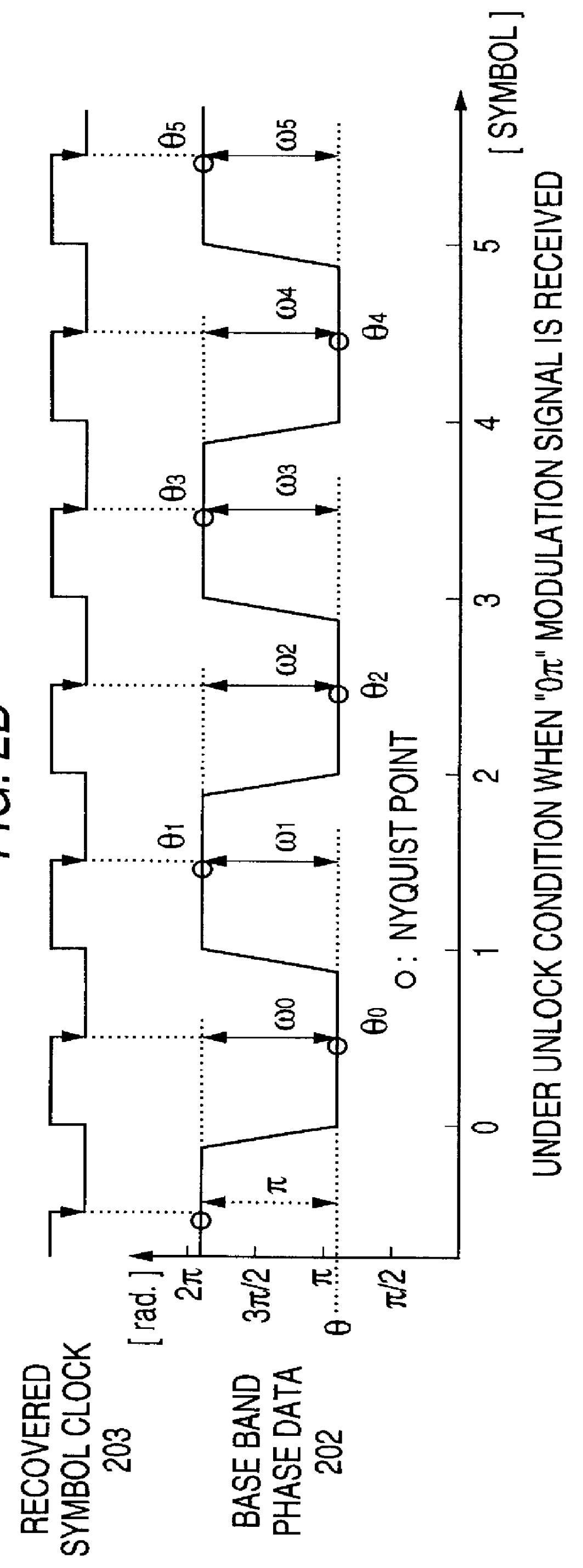
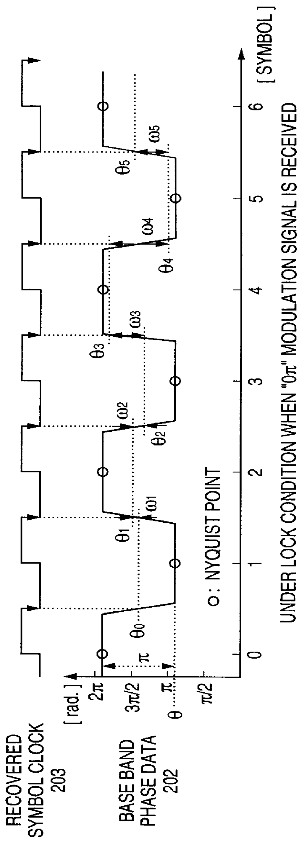
In the embodiment 1, the timing phase synchronization detecting circuit averages the phase variation amount from the baseband phase data 202, and judges as to whether or not the timing phase synchronization can be established based on the predetermined value and the comparison result.

In this embodiment 2, the timing phase synchronization detecting circuit averages a difference value between a phase variation amount of a rising edge and a phase variation amount of a falling edge from the baseband phase data 202, and judges as to whether or not the timing phase synchronization can be established based on a predetermined value and the comparison result.

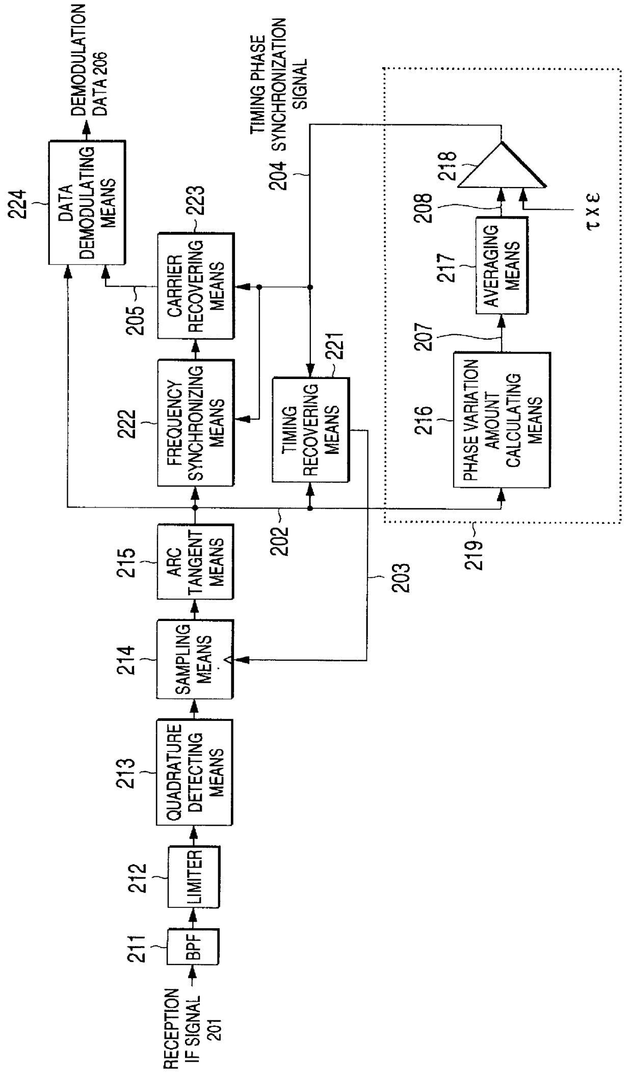
FIG. 5 is a structural diagram for indicating a timing phase synchronization detecting circuit and a demodulator with employment of this timing phase synchronization detecting circuit, according to this embodiment 2.

In this drawing, reference numeral 301 shows a phase variation amount of a rising edge; reference numeral 302...

embodiment 3

(EMBODIMENT 3)

In the embodiment 3, the timing phase synchronization detecting circuit averages the difference value between the phase variation amount of the rising edge ad the phase variation amount of the falling edge from the baseband phase data 202, and judges as to whether or not the timing phase synchronization can be established based on a predetermined value and the comparison result.

In accordance with this embodiment, a timing phase synchronization detecting circuit is operated at a rate two times higher than a symbol rate to perform a differentiation and an averaging operation between a rising edge phase variation amount and a falling edge phase variation amount from the baseband phase data 202.

FIG. 12 is a structural diagram for indicating a timing phase synchronization detecting circuit and a demodulator with employment of this timing phase synchronization detecting circuit, according to this embodiment 3.

In this drawing, reference numeral 403 shows a differentiated phas...


PUM


Abstract

A demodulator is made compact, and with a simple circuit arrangement, and also having a better bit error rate characteristic. A timing phase synchronization detecting circuit 219 judges any one of the following two conditions based upon baseband phase data 202, i.e., an UNLOCK (timing phase asynchronous) condition, and a LOCK (timing phase synchronous) condition. Based upon the judgement result of the timing phase synchronization detecting circuit 219, in a timing recovering means 221, a frequency range of a PLL (phase synchronization loop) is variable, whereas the number of data entered within 1 symbol time is variable in a frequency synchronizing means 222 and a carrier recovering means 223. A data demodulating means 224 outputs demodulation data 206 in response to baseband phase data 202 and a recovery carrier signal 205.

Description

1. Field of the InventionThe present invention is related to an improvement of a timing phase synchronization detecting circuit and a demodulator in a wireless (radio) communication field.2. Description of the Related ArtFIG. 13 is a structural diagram for representing a conventional timing phase synchronization detecting circuit described in, for instance, U.S. Pat. No. 4,675,558.In FIG. 13, reference numeral 101 shows a rectangular input signal having either a value of "A" (symbol "A" being a positive value) or a value of "-A"; reference numeral 102 indicates a clock; reference numeral 103 represents a timing phase synchronization signal for indicating as to whether or not a timing phase synchronization can be established between a Nyquist point of the input signal 101 and the clock 102; and reference numeral 111 shows a low-pass filter. Also, reference numeral 104 indicates a signal obtained by filtering the input signal 101 by the low-pass filter 111; reference numeral 131 denot...

Claims


Application Information

Patent Timeline
Patent Type & Authority Patents(United States)
IPC IPC(8): H04L27/233H04L7/033H03L7/08H03L7/095H03L7/107H04L7/04H04L27/00H04L27/22H04L7/00
CPCH04L7/033H04L27/2332H03L7/095H03L7/107H04L7/046H04L2027/003H04L2027/0036H03L7/1075
Inventor OKUBO, SEIJIFUJIMURA, AKINORIMIYAKE, MAKOTO
Owner MITSUBISHI ELECTRIC CORP
Why Eureka
Try Eureka