Infra-red stealth masking device (IRSMD)

a masking device and infra-red technology, applied in the field of jet engines, can solve problems such as fire hazards, power loss and heat build-up, and turbine penalties

Inactive Publication Date: 2000-08-08
SAWRUK STEPHEN D
View PDF14 Cites 8 Cited by
  • Summary
  • Abstract
  • Description
  • Claims
  • Application Information

AI Technical Summary

Benefits of technology

Consequently, it is an object of the present invention to provide an exhaust duct design for jet engines which will significantly cool exhaust gases to as near the ambient air temperature surrounding the aircraft as possible.
It is yet another object of the present invention to provide an exhaust duct configured to reduce exhaust decibel levels.
It is still another object of the present invention to provide an exhaust duct of high durability with regards to high temperature and pressure variations.
It is yet another object of the present invention to provide an exhaust duct which will have minimal effect on turbine back-pressure.
These and other objects are achieved by the present invention which provide a geodesic matrix within the entire exhaust duct containing injector nozzles for cryogenic coolant. The matrix will also provide external and internal saw-toothed triangular ridges. By such arrangement, the internal surface area of the exhaust duct in direct contact with hot gases will greatly increase, thus maximizing heat transfer. At the same time, the internal triangular ridges, with increased surface area, will transfer this heat efficiently to coolant chambers within the matrix.

Problems solved by technology

Plug-type exhaust systems also create turbine back-pressure penalties which result in power loss and heat build-up.
This system can cause a fire hazard and more significantly does not suppress infrared emmissions.
All of the above cited references either do not address a solution for infrared thermal suppression, have limited-efficiency or cause turbine penalties.
Furthermore, all of the systems cited use hazardous propellants as cooling mediums as opposed to inflammable cryogenic mediums.
Most importantly prior art depicts the exhaust duct as having smooth tapered walls which severely limit heat-transfer rates due to their limited surface area which is the medium for heat to coolant transfer.
Other prior art known to the inventor does not disclose a device which will dissipate and significantly cool reaction motor exhaust, reduce exhaust decibels, and have no negative effect upon thrust and performance with regards to increasing turbine back-pressure.
Improvements have been made in all areas with the exception of Infra-Red (IR) suppression devices which are limited in efficiency.
The utility of the device is particularly great in Military Aircraft where detection by hostile forces is a prime and unwanted factor.

Method used


Image

  • Infra-red stealth masking device (IRSMD)
  • Infra-red stealth masking device (IRSMD)
  • Infra-red stealth masking device (IRSMD)

Examples


Embodiment Construction

, the drawings, and claims appended herewith.

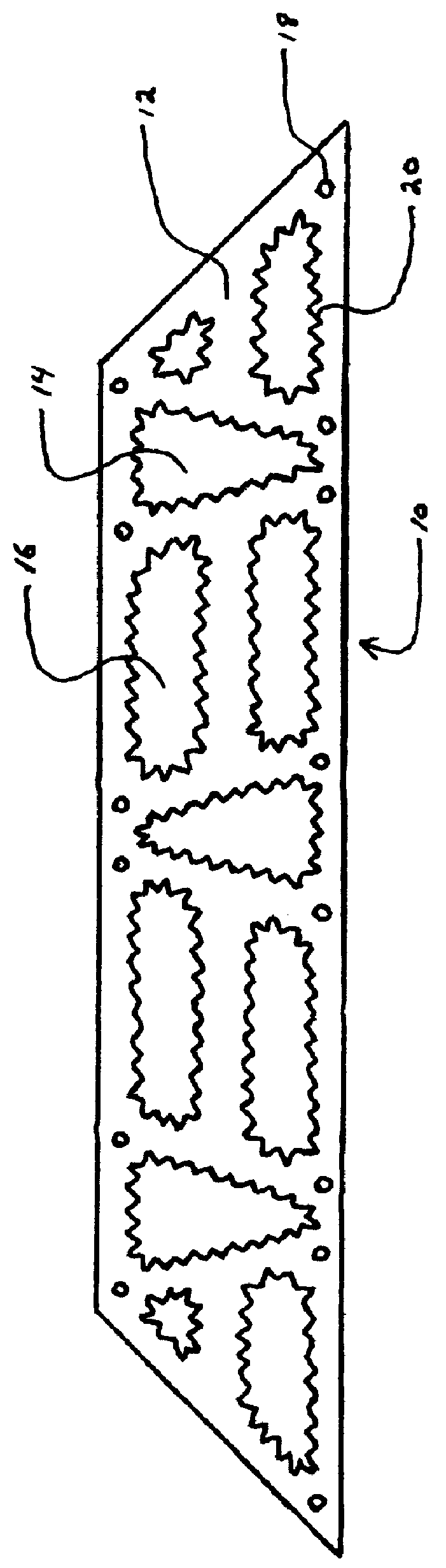
FIG. 1. is a posterior view of the distal end of the exhaust duct having a geodesic matrix pattern and external saw-toothed configuration constructed according to the present invention.

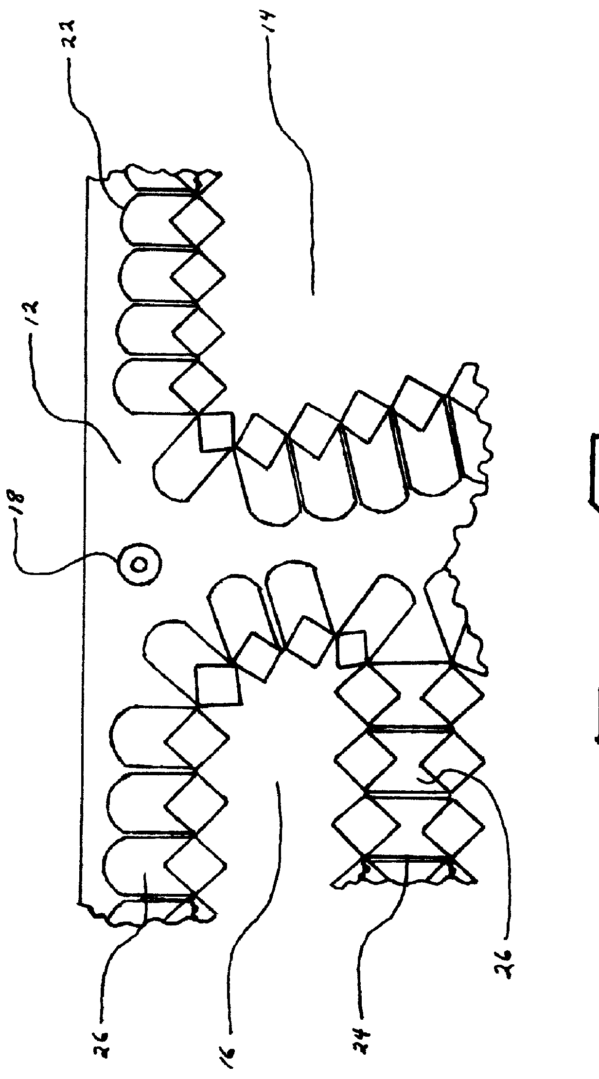
FIG. 2. is an enlarged cross sectional view of a segment of the exhaust duct wall and coolant chambers constructed according to the preferred embodiment of the present invention.

FIG. 3. is a further enlarged cross-sectional view of a segment of the exhaust duct wall and coolant chamber constructed according to the preferred embodiment of the present invention.

FIG. 4. is another enlarged cross-sectional view of a segment of the exhaust duct wall and coolant chamber constructed according to the preferred embodiment of the present invention.

FIG. 5. is an enlarged cross-sectional view of a combustion wall and coolant channel constructed according to prior art.

FIG. 6. is another enlarged cross-sectional view of a combustion wall and coolant channel constructed a...


PUM


Abstract

An Infra-Red suppression device composed of systems designed to alter the infra-red spectrum bands produced by the exhaust plume and airframe friction in order to render infra-red seekers, both active and passive, and infra-red homing missiles ineffective, therefore substantially increasing air-craft and crew survivability, and the BET or battle extension time.

Description

1. Field of InventionThis invention relates generally to jet engines and more particularly to thrust chamber, reaction motor exhaust duct, and tailpipe cooling through a combination of heat dissipation via conduction transmission through a cryogenic non-propellant medium, injection of a cryogenic non-propellant medium, and ambient ram-air injection.2. Description of the Prior ArtThe plug-type exhaust system is widely known and it's main design feature is to block direct radiation of engine infrared, these systems solely rely upon air rammed by the fan or a ducted fan engine, collected by scoops to cool hot metal parts to reduce exhaust heat transmission to these parts. Plug-type exhaust systems also create turbine back-pressure penalties which result in power loss and heat build-up. Turbine cooling results in higher thrust output and efficiency in addition to cooling of the critical turbine blades. This has been accomplished by injecting a cryogenic fuel into the combustion chamber....

Claims


Application Information

Patent Timeline
Patent Type & Authority Patents(United States)
IPC IPC(8): B64D33/04B64D33/00F02K1/82F02K1/00F41H3/00
CPCB64D33/04F02K1/825F41H3/00
Inventor SAWRUK, STEPHEN D.
Owner SAWRUK STEPHEN D
Why Eureka
Try Eureka