Method of drawing fiber continuously by butt welding optical fiber preforms

a technology of fiber and preform, which is applied in the field of fiber drawing method, can solve the problems of degrading attenuation parameters of optical fiber, giving rise to pollution of the side surfaces of optical fiber preform, etc., and achieves the effect of mitigate the above-described drawbacks

Inactive Publication Date: 2000-08-08
ALCATEL LUCENT SAS
View PDF6 Cites 31 Cited by
  • Summary
  • Abstract
  • Description
  • Claims
  • Application Information

AI Technical Summary

Benefits of technology

An object of the invention is to provide a fiber-drawing method that mitigates the above-described drawbacks.

Problems solved by technology

Firstly, the displacement of the two preforms at a certain speed through the fixed welding station gives rise to heating of the preforms upstream and downstream from the two ends to be welded together. That surplus heat propagates axially along the preforms and contributes to extending the zone affected by the welding. When the preforms are drawn down, this zone often gives rise to an optical fiber that has degraded attenuation parameters, and that must be rejected from the output of the fiber-drawing method.
Secondly, the use of a furnace or of an annular torch as a heat source gives rise to pollution of the side surfaces of the preforms as they pass through the welding station.

Method used


Image

  • Method of drawing fiber continuously by butt welding optical fiber preforms

Examples


Embodiment Construction

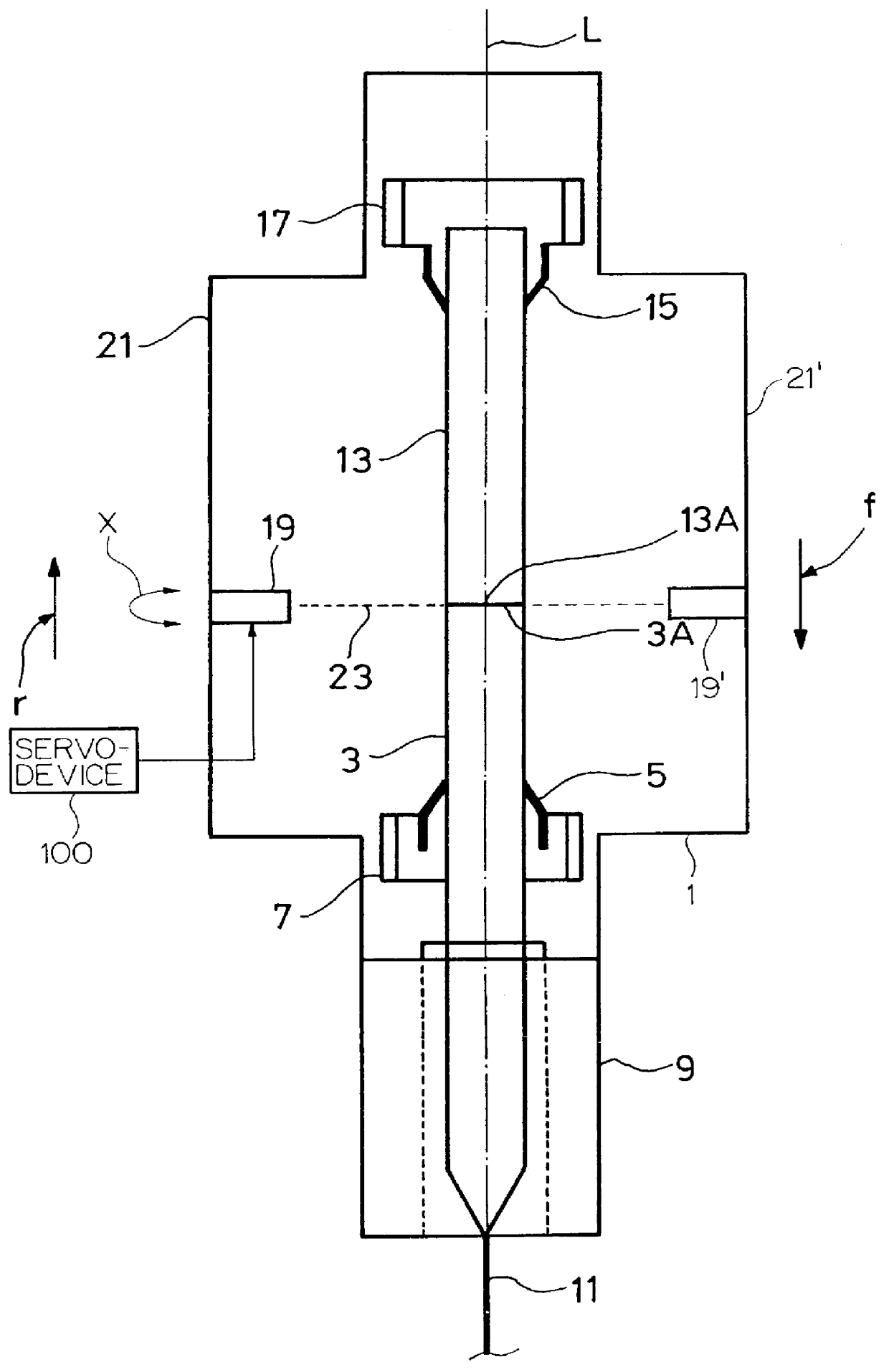
A method of drawing fiber continuously from preforms for manufacturing an optical fiber is implemented (sole FIGURE) by means of a preform-lowering machine 1 for displacing a first preform 3 in translation along a fiber-drawing axis L, which preform is fixed in a chuck 5 secured to a first carriage 7 mounted to move along the fiber-drawing axis. The first preform 3 is lowered by the first carriage 7 through a fiber-drawing furnace 9 disposed along the fiber-drawing axis L so as to be heated and drawn into an optical fiber 11 received by a fiber-receiving reel (not shown).

A second preform 13 is displaced in translation along the fiber-drawing axis L by means of the preform-lowering machine 1 by being fixed in a chuck 15 secured to a second carriage 17 mounted to move along the fiber-drawing axis.

Both carriages 7 and 17 are displaced in the fiber-drawing direction, indicated by arrow f in the FIGURE, at the same speed of translation V. The second preform 13 is placed in the preform-lo...


PUM

PropertyMeasurementUnit
heightaaaaaaaaaa
speedaaaaaaaaaa
sizeaaaaaaaaaa

Abstract

In the method of drawing fiber continuously from preforms for manufacturing an optical fiber, a first preform is displaced along a fiber-drawing axis and is drawn into an optical fiber through a fiber-drawing furnace disposed on the fiber-drawing axis, and a second preform is displaced along the fiber-drawing axis, which second preform is butt welded to the first preform so as to be drawn into an optical fiber following on from the first fiber. The two preforms are butt welded, i.e. they are welded together end-to-end, by displacing at least one power laser along the fiber-drawing axis, and by servo-controlling the displacement of said laser to the displacement of the two preforms so as to maintain a laser beam emitted by the power laser at the same height as the two ends to be welded together, thereby making it possible to reduce considerably the size of the zone affected by the welding, and to avoid polluting the side surfaces of the two preforms upstream and downstream from the weld.

Description

The invention relates to a method of drawing fiber continuously from preforms for manufacturing an optical fiber, in which method a first preform is displaced along a fiber-drawing axis and is drawn into an optical fiber through a fiber-drawing furnace disposed on the fiber-drawing axis, and a second preform is displaced along the fiber-drawing axis, which second preform is butt welded to the first preform so as to be drawn into an optical fiber following on from the first preform.A method of this type is known in particular from U.S. Pat. No. 4,407,667 published on Oct. 4, 1983 and claiming priority from French Patent Application FR 80 17005 filed on Jul. 31, 1980. The preforms are in the form of core rods designed to be built up while they are being displaced along the fiber-drawing axis, prior to being drawn into optical fiber. The core rods are butt welded, i.e. welded together end-to-end, by a welding station which is fixed relative to the fiber-drawing axis, and which comprise...

Claims


Application Information

Patent Timeline
Patent Type & Authority Patents(United States)
IPC IPC(8): C03B37/027C03B37/02G02B6/00
CPCC03B37/02736C03B37/075
Inventor MAZABRAUD, PASCALALAMI NOUREDDINE, ABDERRAHMAN
Owner ALCATEL LUCENT SAS
Why Eureka
Try Eureka