System and method for atrial autocapture in single-chamber pacemaker modes using far-field detection

a single-chamber pacemaker and autocapture technology, applied in the field of implantable cardiac stimulation devices, can solve the problems of shortening the useful life of the pacemaker, discomfort for patients forced to take, and eventually suffering from capture loss

Inactive Publication Date: 2000-08-08
PACESETTER INC
View PDF6 Cites 187 Cited by
  • Summary
  • Abstract
  • Description
  • Claims
  • Application Information

AI Technical Summary

Benefits of technology

The disadvantages and limitations discussed above are overcome by the present invention. In accordance with the invention, a system and method are provided for automating verification of proper atrial capture of pacing pulses generated by a patient's implantable cardiac stimulation device by sensing and identifying a far-field ventricular signal resulting from a ventricular contraction that follows a successfully captured atrial stimulation pulse. The system and method of the present invention compensate for effects of polarization and noise on the identified far-field signal and do not require use of special dedicated circuitry or special sensors to implement the automated procedure. All of the aforesaid advantages and features are achieved without incurring any substantial relative disadvantage.
In a first embodiment of the invention, the pacemaker delivers an atrial stimulation pulse and then samples a resulting far-field ventricular signal during a predetermined far-field interval window that is centered at the expiration of a predetermined window delay. The pacemaker then compares the far-field signal sample to a predetermined far-field signal recognition template to verify whether the far-field signal sample morphology corresponds to a far-field R-wave that is expected to follow a successfully captured atrial stimulation pulse. If the far-field signal sample is approximately equal to the far-field signal recognition template, then atrial capture is deemed verified. Otherwise, the pacemaker performs an atrial stimulation energy determination procedure. This embodiment of the invention is preferably implemented in a pacemaker that is equipped with special electrodes and / or circuitry for reducing or eliminating noise and polarization signals that occur after delivery of atrial stimulation pulses.
The system and method of the present invention thus automatically verify atrial capture and, when necessary, automatically determine a proper atrial stimulation energy of the patient's pacemaker, without requiring dedicated or special circuitry and / or sensors.

Problems solved by technology

The earliest pacemakers had a predetermined and unchangeable stimulation energy, which proved to be problematic because the capture threshold is not a static value and may be affected by a variety of physiological and other factors.
As a result, some patients eventually suffered from loss of capture as their pacemakers were unable to adjust the pre-set stimulation energy to match the changed capture thresholds.
However, this approach resulted in some discomfort to patients who were forced to endure unnecessarily high levels of cardiac stimulation.
Furthermore, such stimulation pulses consumed extra battery resources, thus shortening the useful life of the pacemaker.
While the adjustable pacing energy feature proved to be superior to the previously known fixed energy, some significant problems remained unsolved.
However, many of these advanced pacemakers require additional circuitry and / or special sensors that must be dedicated to capture verification.
This requirement increases the complexity of the pacemaker system and reduces the precious space available within a pacemaker's casing, and also increases the pacemaker's cost.
However, it is for several reasons very difficult to detect a true evoked response.
First, because the atrial evoked response is a relatively small signal, it may be obscured by a high energy A-pulse and therefore difficult to detect and identify.
Second, the signal sensed by the pacemaker's sensing circuitry immediately following the application of a stimulation pulse may be not an evoked response but noise--either electrical noise caused, for example, by electromagnetic interference, or myocardial noise caused by random myocardial or other muscle contraction.
Another signal that interferes with the detection of an evoked response, and potentially the most difficult for which to compensate because it is usually present in varying degrees, is lead polarization.
Unfortunately, because the evoked response is sensed through the same lead electrodes through which the stimulation pulses are delivered, the resulting polarization signal, also referred to herein as an "afterpotential", formed at the electrode can corrupt the evoked response that is sensed by the sensing circuits.
This undesirable situation occurs often because the polarization signal can be three or more orders of magnitude greater than the evoked response.
Furthermore, the lead polarization signal is not easily characterized; it is a complex function of the lead materials, lead geometry, tissue impedance, stimulation energy and other variables, many of which are continually changing over time.
In each of the above cases, the result may be a false positive detection of an evoked response.
Such an error leads to a false capture indication, which in turn leads to missed heartbeats--a highly undesirable and potentially life-threatening situation.
Another problem results from a failure by the pacemaker to detect an evoked response that has actually occurred.
In that case, a loss of capture is indicated when capture is in fact present--also an undesirable situation that will cause the pacemaker to unnecessarily invoke the pacing energy determination function in a chamber of the heart.
Furthermore, the polarization signal formed at the atrial lead electrode may obscure and / or distort the far-field R-wave signal, even if it were sensed.

Method used


Image

  • System and method for atrial autocapture in single-chamber pacemaker modes using far-field detection
  • System and method for atrial autocapture in single-chamber pacemaker modes using far-field detection
  • System and method for atrial autocapture in single-chamber pacemaker modes using far-field detection

Examples


first embodiment

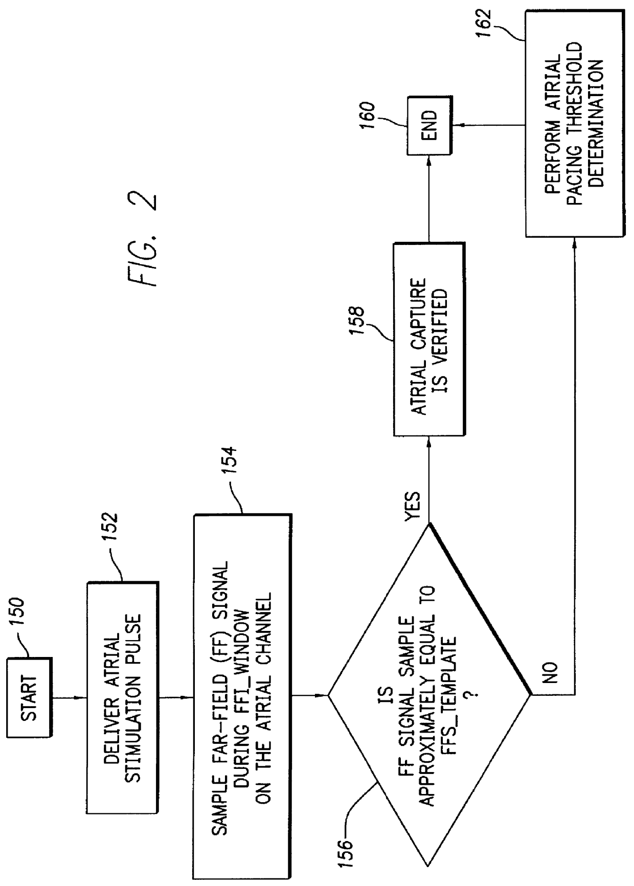
FIG. 2 depicts a logic flow diagram representing a control program for controlling the atrial capture verification and atrial pacing energy determination procedure executed by the control system 30 in accordance with the present invention. The control program of FIG. 2 is preferably used in a pacemaker that is equipped with special electrodes and / or circuitry for reducing or eliminating noise and polarization signals that occur after delivery of stimulation pulses.

Preferably, the control system 30 periodically invokes the control program to perform the capture verification test and, when necessary or appropriate, the atrial pacing energy assessment test in the atrial chamber of the heart 24. The frequency with which these tests are to be performed are preferably programmable parameters set by the medical practitioner using the external programmer 100 when the patient is examined during an office visit or remotely via the communication link 112. The appropriate testing frequency para...

second embodiment

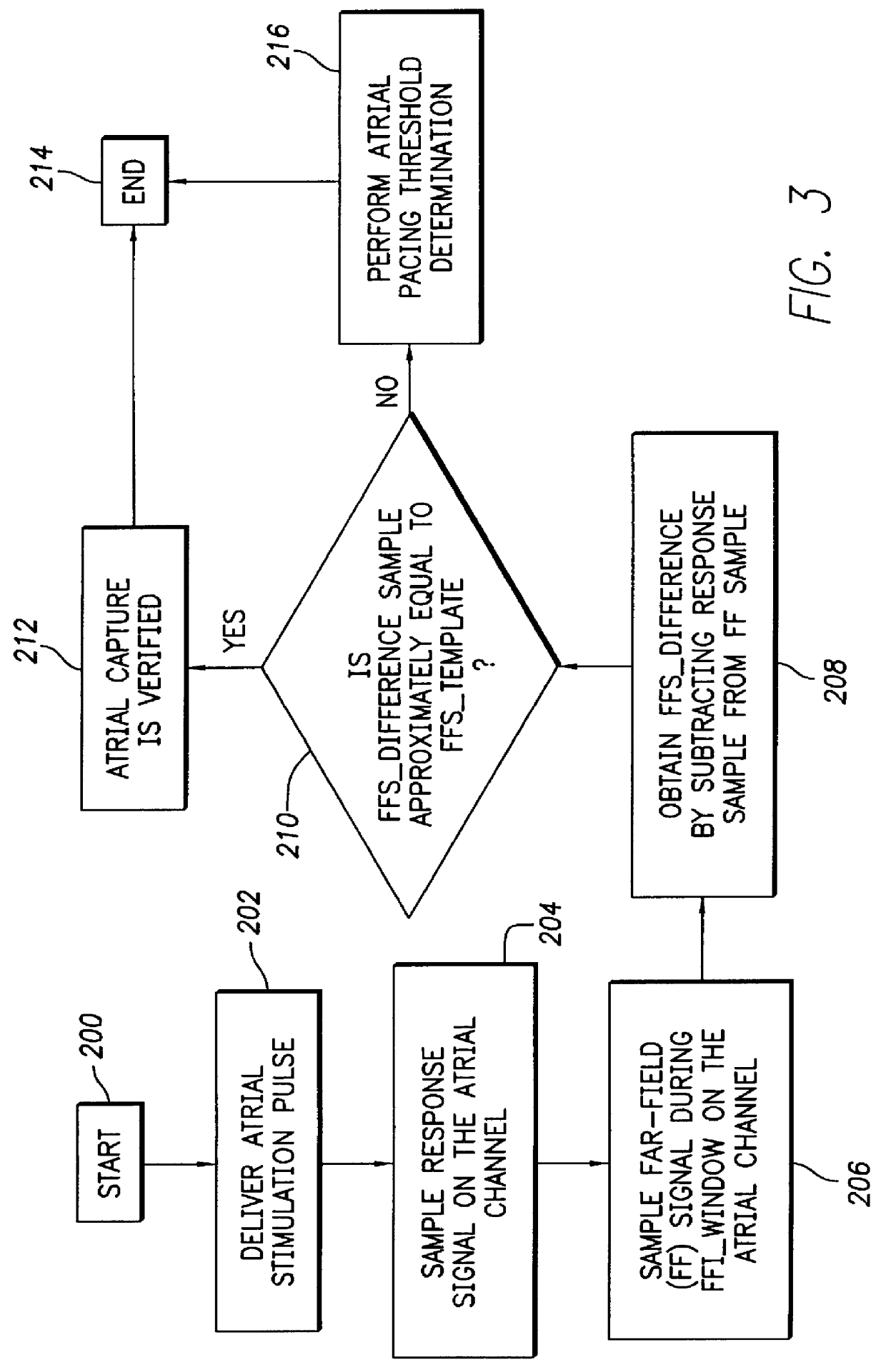
FIG. 3 depicts a logic flow diagram representing a control program for controlling the atrial capture verification and atrial pacing energy determination procedure executed by the control system 30 in accordance with the present invention. Unlike the control program of FIG. 2, the control program of FIG. 3 may be used in a pacemaker that is not equipped with special electrodes and / or circuitry for reducing or eliminating polarization signals that occur after delivery of stimulation pulses. As with the previously described control program of FIG. 2, the control system 30 periodically invokes the alternative control program of FIG. 3 to perform the capture verification test and, when necessary, the atrial pacing energy assessment test in the atrial chamber of the heart 24.

After the atrial capture verification test of FIG. 3 begins at a step 200, the control system 30 at a step 202 causes the atrial pulse generator 16 to deliver a stimulation pulse to the atrial chamber. When delivered...


PUM


Abstract

An implantable pacemaker automatically verifies atrial capture and performs atrial stimulation energy assessment when atrial capture is absent. The pacemaker delivers a stimulation pulse in the atrial chamber of the heart and samples the resulting far-field signal from the ventricular chamber during a predetermined far-field interval window. The pacemaker then compares the far-field signal sample to a predetermined far-field signal recognition template. If the far-field signal sample is approximately equal to the far-field signal recognition template, then atrial capture is deemed verified; otherwise, the pacemaker performs an atrial stimulation energy determination. Optionally, the pacemaker automatically determines the timing of the far-field interval window and defines the far-field signal recognition template.

Description

FIELD OF THE INVENTIONThe present invention relates in general to implantable cardiac stimulation devices, including bradycardia and antitachycardia pacemakers, defibrillators, cardioverters and combinations thereof that are capable of measuring physiological data and parametric data pertaining to implantable medical devices. More particularly, this invention relates to a system and method for automating detection of atrial capture in an implantable cardiac stimulation device using far-field signal detection.BACKGROUND OF THE INVENTIONImplantable medical devices, such as pacemakers, defibrillators, and cardioverters (collectively referred to herein as implantable cardiac stimulating devices), are designed to monitor and stimulate the heart of a patient that suffers from a cardiac arrhythmia. Using leads connected to a patient's heart, these devices typically stimulate the cardiac muscles by delivering electrical pulses in response to measured cardiac events that are indicative of a ...

Claims


Application Information

Patent Timeline
Patent Type & Authority Patents(United States)
IPC IPC(8): A61N1/37A61N1/362
CPCA61N1/3712A61N1/3714
Inventor SLOMAN, LAURENCE S.
Owner PACESETTER INC
Why Eureka
Try Eureka