Method and device for detecting a state of charge of a battery assembly, and battery assembly charge and discharge control device

a battery and state detection technology, applied in the direction of electric devices, propulsion parts, propulsion using engine-driven generators, etc., can solve the problems of low limit value, gradual enlargement, and change of charged amoun

Inactive Publication Date: 2000-08-15
TOYOTA JIDOSHA KK +2
View PDF13 Cites 58 Cited by
  • Summary
  • Abstract
  • Description
  • Claims
  • Application Information

AI Technical Summary

Problems solved by technology

Furthermore, the lower limit value is set considering the electric power necessary during the starting up of the combustion engine, and the like.
However, the variation in charged amount changes with the elapse of the operating time of a battery, and generally gradually enlarges.
Previously, there has been such a problem that as will be described more fully below, that the detection of the charged amount is not properly performed and the control of charge is not properly performed since the change of the variation is not considered.
However, this assumption that the area m' can move to the position shown by the dotted line is not correct.
Such control negatively effects drivability.
If a shift from charge to discharge is suddenly performed, the distribution of the driving force also suddenly shifts, causing the driving force to shift in stages and giving the occupants an uncomfortable feeling.
These problems also arise similarly during the discharge.
That is, the occupants may feel discomfort because of a sudden shift from discharge to charge.
These problems arise because the charged amount is not accurately detected.
When the variation becomes large, a further problem arises.
This results in that a contradiction arises in control and a suitable control cannot be performed.
In such a case, discharge and charge are repeated without achieving the control target, and consequently, repeated switching between charge and discharge may arise.
As descried above by using a concrete example, if the variation changes, the charged amount is not properly detected, and the control of charge may not properly be performed.
However, approaching the problem in this way results in the upper or lower limits of the charged amount being wastefully limited and in the under utilization of battery performance.
However, the variation in the charged amount of a battery is not considered, and the detected allowance of discharge is not accurate.
Especially, problems such as described above are obvious in a battery having a charging characteristic similar to that of a nickel hydrogen battery (NiMH).
IV judgment is difficult in the area where the voltage is constant, and the area where the IV judgment can suitably be performed, is limited to the areas of both ends.
Furthermore, in the representative value X for the tracing of the charged amount, an error according to the change (enlargement) of the variation may arise.
Therefore, for a nickel hydrogen or similar battery having a charging characteristic as shown in FIG. 2, it has been difficult to detect the variation in charged amount while the battery is used.
If the detection result of the movable range having such an error is used, the total of the real movable range cannot be utilized for the charge and discharge control.

Method used


Image

  • Method and device for detecting a state of charge of a battery assembly, and battery assembly charge and discharge control device
  • Method and device for detecting a state of charge of a battery assembly, and battery assembly charge and discharge control device
  • Method and device for detecting a state of charge of a battery assembly, and battery assembly charge and discharge control device

Examples


embodiment 1

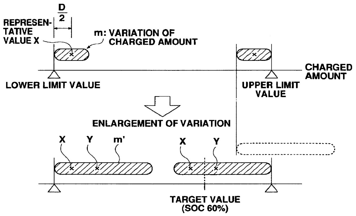
If the battery temperature is in said range of allowable temperature during the IV judgments of both the upper limit value and the lower limit value, the variation in charged amount can be found similarly to Then, on the basis of the detected width of the variation, the amount of the state of charge of the present invention (N-SOC) is calculated, control of charge and discharge of the battery 50 is performed based on that N-SOC.

On the other hand, if the battery temperature is not in said range of allowable temperature during the IV judgment of at least either of the upper limit value or the lower limit value, the calculation of the width of the variation by using the integrated value of the current, and the calculation of the movable range based on the width of the variation are not performed. Since these numerical values are not renewed, the previously detected and used width of the variation and movable range (existing values) are continuously used. If an IV judgment in said rang...

embodiment 2

As described above, in Embodiment 2, since the calculation of the variation in charged amount or the movable range is not performed in the range of temperature where the accuracy of the IV judgment is low, the accuracy of the calculation of these numerical values can be improved.

Since there are errors in the IV judgment or the integration of the current used in Embodiment 1, the variation in charged amount or the movable range may be estimated to be less than the actual amounts because of those errors. In such a case, the charged amount is controlled so that N-SOC may fluctuate in the movable range estimated to be less. Accordingly, the whole of the actual movable range is not utilized, and the performance of a battery cannot completely be utilized. Furthermore, the fact that N-SOC fluctuates in the movable range estimated to be less, means that thereafter it is difficult for the IV judgment of the upper limit value or the lower limit value to arise and the reobtaining of the variat...

embodiment 3

In Embodiment 3, in order to avoid such a situation that the total of the movable range cannot be used as mentioned above, the battery ECU 68 performs the following control:

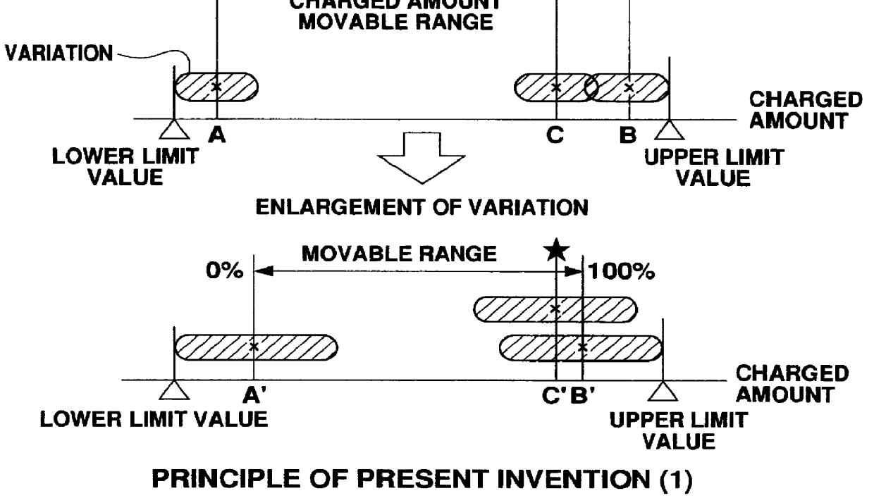
The battery ECU 68 first detects the variation in charged amount by performing the IV judgments of the upper limit value and the lower limit value, as described in Embodiment 1. From this detected value of the variation, the movable range is calculated. The scale of the movable range is, as shown by FIG. 10 and Expression (2), 3.9-DAHR (AH). Here, DAHR is a detected value of the width of the variation in charged amount. Then, on the basis of this movable range, N-SOC at each time is calculated according to Expression (2).

As a feature of Embodiment 3, the battery ECU 68 gradually enlarges said detected movable range with the elapse of time. This enlargement means the recovery of the movable range. Accompanied with the enlargement, the variation DAHR is reduced. The processing of enlargement is performed so that th...


PUM

PropertyMeasurementUnit
state of chargeaaaaaaaaaa
timeaaaaaaaaaa
temperatureaaaaaaaaaa

Abstract

Variation of the charged amount among battery blocks composing a battery assembly is detected. By subtracting the detected value of the variation from the width between the upper limit value and the lower limit value of the charged amount, the movable range of the charged amount is found. The position of the present charged amount is detected as the state of charge. For example, it is arranged that both ends of the movable range are 0% and 100%, and that the movable range is the full scale. Then, the position of the charged amount on this scale is specified by the ratio %. The detection of the state of charge in which the variation in charged amount and the change of the movable range are considered, is performed, and on the basis of this state of charge, a preferable charge and discharge control is performed.

Description

1. Field of the InventionThe present invention relates to the detection of the state of charge of a battery assembly, and especially relates to a method and device by which the state of charge can accurately be detected, even if the variation in charged amount among batteries composing a battery assembly becomes large. Furthermore, the present invention relates to a device by which said variation in charged amount can easily be detected.2. Description of the Related ArtA typical electric motor car in which an electric motor provides the driving force has a secondary battery (hereafter referred to simply as a battery), and the electric motor is driven by the electric power charged in this battery. Here, a hybrid powered automobile which is a type of electric motor car, will be described.A hybrid powered automobile has an electric motor and a combustion engine, and further includes an electric generator. The electric generator generates electric power by being driven by the combustion...

Claims


Application Information

Patent Timeline
Patent Type & Authority Patents(United States)
IPC IPC(8): B60K6/00B60K6/04G01R31/36B60L3/00B60L11/18B60W10/08B60W10/26B60W20/00H01M10/44H01M10/48H02J7/00H02J7/02
CPCB60K6/365B60L11/123B60L11/14B60L11/1861B60L11/1872B60L15/20B60W10/08B60W10/26G01R31/3624G01R31/3648G01R31/3658B60W20/00B60W2510/244Y02T10/6217Y02T10/7005Y02T10/7044Y02T10/705Y02T10/7077Y02T10/7275Y10S903/91Y02T10/72G01R31/3842G01R31/396B60L50/61B60L50/16B60L58/25B60L58/15Y02T10/62Y02T10/70Y02T10/64Y02T10/7072B60W20/13B60K6/445
Inventor KIKUCHI, YOSHIAKISEKIMORI, TOSHIYUKIASAKAWA, FUMIHIKOUKITA, SUSUMUSHOJI, YOSHIMINAKANISHI, TOSHIAKIKIMURA, TADAOKATOH, TOMOYA
Owner TOYOTA JIDOSHA KK
Why Eureka
Try Eureka