Ostomy appliance faceplate with barrier layer, extended covering layer, and unitary protective release sheet and method of making

a technology of skin barrier and extended covering, applied in the field of faceplate, can solve the problems of increasing manipulative steps, exposing the outer edge of the skin barrier material to possible drying, and relatively expensive molded coverings

Inactive Publication Date: 2000-08-22
HOLLISTER INCORPORAED
View PDF6 Cites 51 Cited by
  • Summary
  • Abstract
  • Description
  • Claims
  • Application Information

AI Technical Summary

Benefits of technology

Cartmell, et al U.S. Pat. No. 5,489,262 discloses a wound dressing having a hydrogel patch and a transparent adhesive-coated backing layer that extends outwardly beyond the outer limits of the hydrogel patch. A unitary and generally planar release sheet covers both the opposite surface of the hydrogel patch and the adhesive coating of that portion of the backing layer extending outwardly beyond the patch; however, a tenting effect results in which an annular zone of entrapped air extends about the patch and may result in undesirable drying during storage of either or both the hydrogel and the adhesive coating of the backing layer immediately surrounding the hydrogel patch.
Accordingly, a main aspect of this invention lies in providing an improved faceplate construction and its method of manufacture. A unitary release sheet protects the bodyside (rear) surfaces of a barrier layer and of an adhesiv...

Problems solved by technology

The need for providing two release sheets, one for the barrier layer and the other for the surrounding adhesive surface of the microporous patch, arises partly from cost and production considerations since the surfaces the respective release sheets cover are offset and therefore cannot easily be protected by a single release sheet and certainly not by one that is planar.
While a molded release covering of developed shape has been disclosed, for example, in Bryson U.S. Pat. No. 4,710,182, such a molded covering is relatively expensive, especially since it is intended primarily to serve a protective function only until the faceplate is to be used, at which time the covering must be removed and discarded.
On the other hand, providing separate protective release sheets increases the manipulative steps required by a user at the time of appl...

Method used


Image

  • Ostomy appliance faceplate with barrier layer, extended covering layer, and unitary protective release sheet and method of making
  • Ostomy appliance faceplate with barrier layer, extended covering layer, and unitary protective release sheet and method of making
  • Ostomy appliance faceplate with barrier layer, extended covering layer, and unitary protective release sheet and method of making

Examples


Embodiment Construction

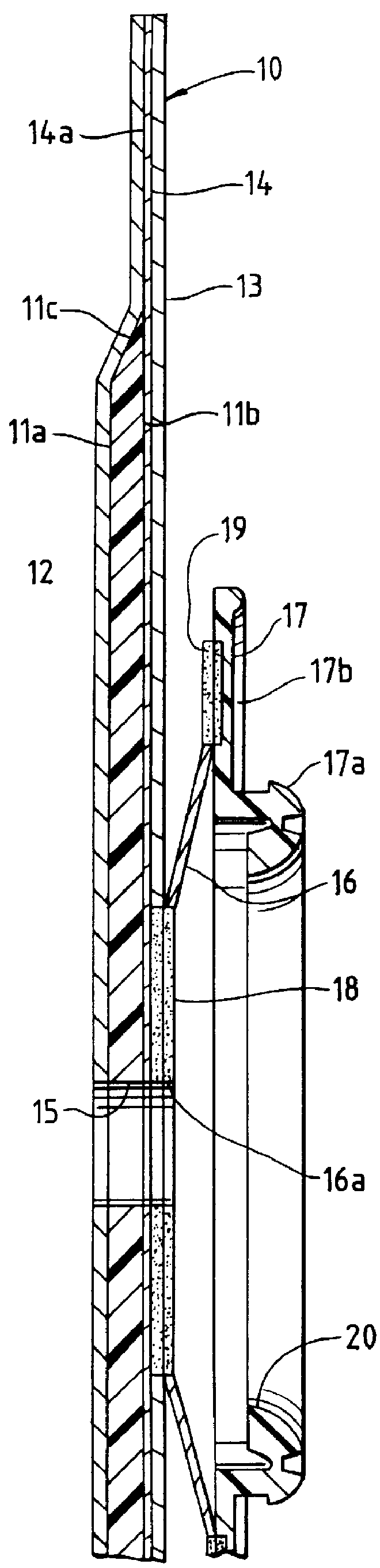
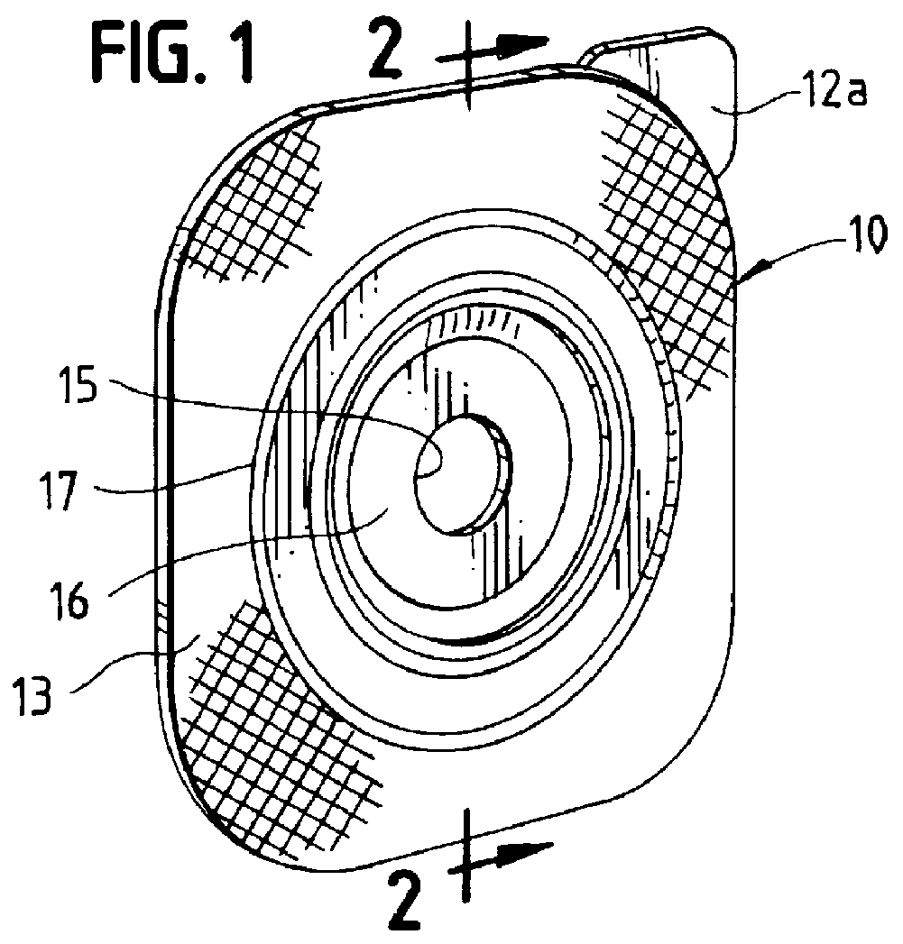
Referring to FIGS. 1 and 2, the numeral 10 generally designates a faceplate for an ostomy appliance. While the faceplate shown is for a two-piece appliance (in which a pouch component, not shown, is adapted to be mechanically coupled to and uncoupled from the faceplate component), faceplate 10 might also be part of a one-piece appliance in which a faceplate and pouch are permanently joined together. The faceplate as shown is generally rectangular (square) in outline with rounded corners, but other shapes, such as circular or oval shape, may be provided. The faceplate includes a barrier layer or wafer 11 of moisture-absorbing adhesive skin barrier material having a bodyside (rear) surface 11a covered by a removable release sheet 12 and an opposite (front) surface 11b covered by an adhesive-coated porous covering layer 13.

The term "skin barrier" is widely used in the medical field, and is so used herein, to refer to any of a variety of materials in which a soft, sticky, and pliant adh...


PUM


Abstract

A faceplate for an ostomy appliance is disclosed in which a unitary release sheet covers both the bodyside (rear) surface of an adhesive skin barrier layer and the surrounding adhesive surface of an outwardly-projecting porous covering layer. The barrier layer is beveled to a feathered outer edge and the release sheet contacts the adhesive surface of the covering layer immediately adjacent the outer edge of said barrier layer. A continuous in-line method for making such faceplates is disclosed.

Description

BACKGROUND AND SUMMARYAlexander U.S. Pat. No. 4,419,100 discloses a two-piece ostomy appliance in which a faceplate component 12 includes a coupling ring 37 attached by thin annular web 42 to a mounting collar 30a which in turn is joined by heat seals 46 and 47 to microporous patch 30. An annular skin barrier layer 32, commonly formed of a hydrocolloid-containing moisture-absorbing and swellable adhesive material having both dry and wet tack, covers the inner portion of patch 30. To protect the bodyside surface of the skin barrier layer and the adhesive coating of that portion of the microporous patch that extends outwardly beyond the skin barrier layer, release sheets 31 and 33 separately cover each of the adhesive surfaces.The need for providing two release sheets, one for the barrier layer and the other for the surrounding adhesive surface of the microporous patch, arises partly from cost and production considerations since the surfaces the respective release sheets cover are off...

Claims


Application Information

Patent Timeline
IPC IPC(8): A61F5/443A61F5/445A61F5/448
CPCA61F5/443A61F5/448
Inventor BOTTEN, RONALD S.LEISE, JR., WALTER F.MCDONALD, JR., JOHN W.
Owner HOLLISTER INCORPORAED
Why Eureka
Try Eureka