Method and apparatus for producing laminate board

Inactive Publication Date: 2000-08-22
TOYO KOHAN CO LTD
View PDF5 Cites 4 Cited by
  • Summary
  • Abstract
  • Description
  • Claims
  • Application Information

AI Technical Summary

Benefits of technology

Furthermore, the apparatus may effectively comprise a presser or pressure roll for increasing the contact force of the laminate roll and the laminate sheet when the laminate sheet, which has passed through the laminate rolls, is pushed aside to one of the laminate rolls.
Since the manufacturing apparatus is provided with a deflector roll to deviate the traveling direction of the laminate sheet which has passed between the couple of laminate rolls, it is possible to deviate the traveling direction without causing any resistance to the traveling of the laminate sheet. Apparatus provided with a guide roll to take the deviated traveling direction back to the original direction can easily be combined with a conventional manufacturing line for a laminate sheet. Further, the apparatus provided with the deflector roll movably arranged in a direction transverse to the original traveling direction of the laminate sheet makes it possible to obtain the most preferable thickness of the melted layer of the film depending on the kind of raw material and the traveling speed of the laminate sheet so that the adhesive strength of the film can be improved to thereby prevent subsequent delamination.

Problems solved by technology

For this reason, it is difficult to perform high speed lamination by the conventional laminating method.
But in this case, cooling by the laminating rolls does not fully effect cooling of the film 102 so that the melted layer 105 may be formed throughout the whole film thickness, thus reducing the strength of the film.
In addition, in a case where the laminate forms a food can and such wholly melted film is located inside of the formed can, and when content is packed and storaged in it, the film is easily cracked by outer impact, which often causes the packed contents to become spoiled.

Method used


Image

  • Method and apparatus for producing laminate board
  • Method and apparatus for producing laminate board
  • Method and apparatus for producing laminate board

Examples


examples 1 to 3

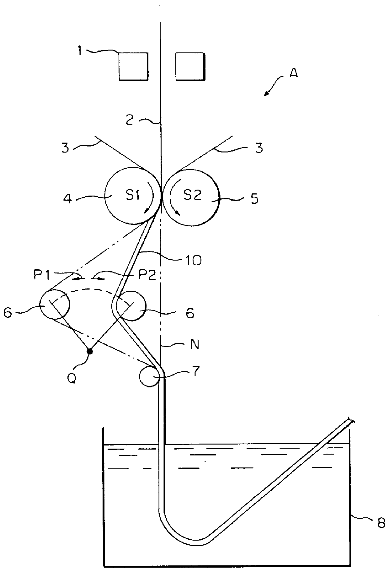
A biaxially oriented polyester thermoplastic resin film having thickness of 25 .mu.m was heat laminated on one side of a strip of electrolytically chromated steel (TFS) having a thickness of 0.2 mm used for can stock using the manufacturing apparatus as shown in FIG. 1. The temperature of the steel strip just before coming to the laminate rolls was about 225.degree. C., and that of the laminate roll spontaneously cooled was about 150.degree. C. The traveling speeds of the laminate sheet were 100, 200 and 400 m / min in Example 1, 2 and 3, respectively. Winding angle for the laminate sheet round the laminate roll was 20.degree. in all examples.

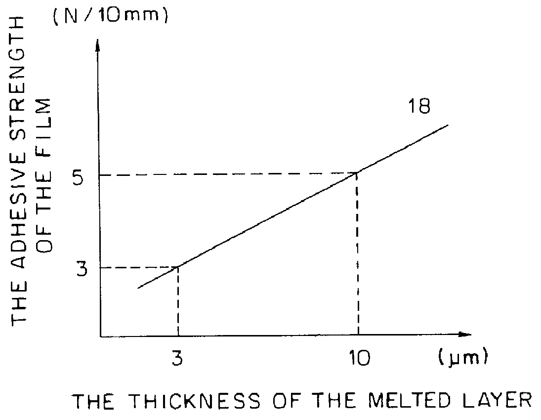
When the laminates thus obtained were formed into a cup having a diameter of 65 mm and a height of 100 mm using a drawability tester, no film crack was caused in any of the examples and 4.0 to 5.6 N / 10 mm of stripping force of the film (adhering strength during forming) was required to strip the film in each example. The original orientation of t...


PUM

PropertyMeasurementUnit
Lengthaaaaaaaaaa
Forceaaaaaaaaaa
Metallic bondaaaaaaaaaa

Abstract

PCT No. PCT / JP95 / 02519 Sec. 371 Date Nov. 25, 1997 Sec. 102(e) Date Nov. 25, 1997 PCT Filed Dec. 8, 1995 PCT Pub. No. WO96 / 17721 PCT Pub. Date Jun. 13, 1996A method of producing a laminate board (10) involves the steps of heating a continuous belt-like metallic sheet (2) by a heating furnace (1), laminating a thermoplastic resin film (3) on at least one of the surfaces of the metallic sheet, pressing and passing both of them between a pair of laminate rolls (4 and 5), and thermally bonding the film (3) to the metallic sheet (2), wherein the laminate sheet (10) coming out from between the pair of laminate rolls (4 and 5) is pushed by a deflector roll (6) in a transverse direction so as to bias the travelling direction towards the laminate roll (4) in contact with the film (3). The invention also discloses an apparatus (A) used for his method.

Description

The present invention relates to a manufacturing method for a laminate sheet and manufacturing apparatus therefor, and more particularly to a manufacturing method for a laminated sheet, in which a thermoplastic resin film is made to contact and be pressed to a heated metal sheet, and a manufacturing apparatus for carrying out the manufacturing method.BACKGROUND TECHNOLOGYAs shown in FIG. 4, there is a well known laminating method in which a metal sheet 101, heated in an oven, is then made to contact thermoplastic resin films 102, and the metal sheet 101 and resin films 102 are both pressed by a couple of laminating rolls (nip rolls) 103 and 104 while the film 102 is partially melted by the heat of metal sheet 101 to adhere to metal sheet 101 (see Laid-Open Japanese Patent Hei 4-201237, for example). In such a laminating method, the thickness of the melted portion of film 102 (thickness of a melted layer), and the adhering strength of film 102 to the metal sheet 101 can be controlled...

Claims


Application Information

Patent Timeline
IPC IPC(8): B32B15/08
CPCB32B15/08B32B37/04B32B37/06B32B38/18Y10T156/1741B32B2309/02B32B2309/06B32B2307/518B32B15/09B32B27/36B32B2309/105B32B15/18
Inventor KAGUMA, NORIAKITANAKA, ATSUOIWASHITA, HIROYUKISAKAMOTO, YOSHIKIINAZAWA, HIROSHI
Owner TOYO KOHAN CO LTD
Why Eureka
Try Eureka