Device for direct electrostatic printing with a conventional printhead structure and AC-coupling to the control electrodes

a printhead and control electrode technology, applied in printing, instruments, optics, etc., can solve the problems of moderate printing speed, easy clogging of printing apertures by toner particles, etc., and achieve high maximum density, low clogging, and high speed

Inactive Publication Date: 2000-08-29
AGFA GEVAERT AG
View PDF15 Cites 3 Cited by
  • Summary
  • Abstract
  • Description
  • Claims
  • Application Information

AI Technical Summary

Benefits of technology

It is an object of the invention to provide a DEP device, i.e. a device for direct electrostatic printing that can print at high speed with low clogging of the control electrodes and with high maximum density and with a high degree of density resolution (i.e. for producing an image comprising a high amount of differentiated density levels) and spatial resolution.

Problems solved by technology

One of the recognised problems with both of these types of printhead structures, the printing apertures are easily clogged by toner particles when the DEP device is used over a longer period of time.
Said edge electrode system proposed in U.S. Pat. No. 5,625,392 suffers however from the drawback that, in order to obtain a good image contrast between image parts of low density and image parts of high density, the overall applied propulsion field between the toner applicator and the receiver on the back electrode must be set to a rather low value, leading to only a moderate printing speed.

Method used


Image

  • Device for direct electrostatic printing with a conventional printhead structure and AC-coupling to the control electrodes
  • Device for direct electrostatic printing with a conventional printhead structure and AC-coupling to the control electrodes
  • Device for direct electrostatic printing with a conventional printhead structure and AC-coupling to the control electrodes

Examples


example 1

The printhead structure.

A printhead structure (106) was made from a polyimide film of 50 .mu.m thickness (106c), double sided coated with a 5 .mu.m thick copper film. The printhead structure (106) had two rows of printing apertures. On the back side of the printhead structure, facing the receiving member substrate, a rectangular shaped control electrode (106a) was arranged around each aperture. Each of said control electrodes was connected over 2 M.OMEGA. resistors to a HV 507 (trade name) high voltage switching IC, commercially available through Supertex, USA, that was powered from a high voltage power amplifier. On the back side of the printhead structure, facing the back electrode, a common shield electrode (106b) was present. The printing apertures were rectangular shaped with dimensions of 200 by 100 .mu.m. The total width of the rectangular shaped copper control electrodes and connecting lines was 80 .mu.m. The width of the aperture in the common shield electrode was 1600 .mu....

example 2

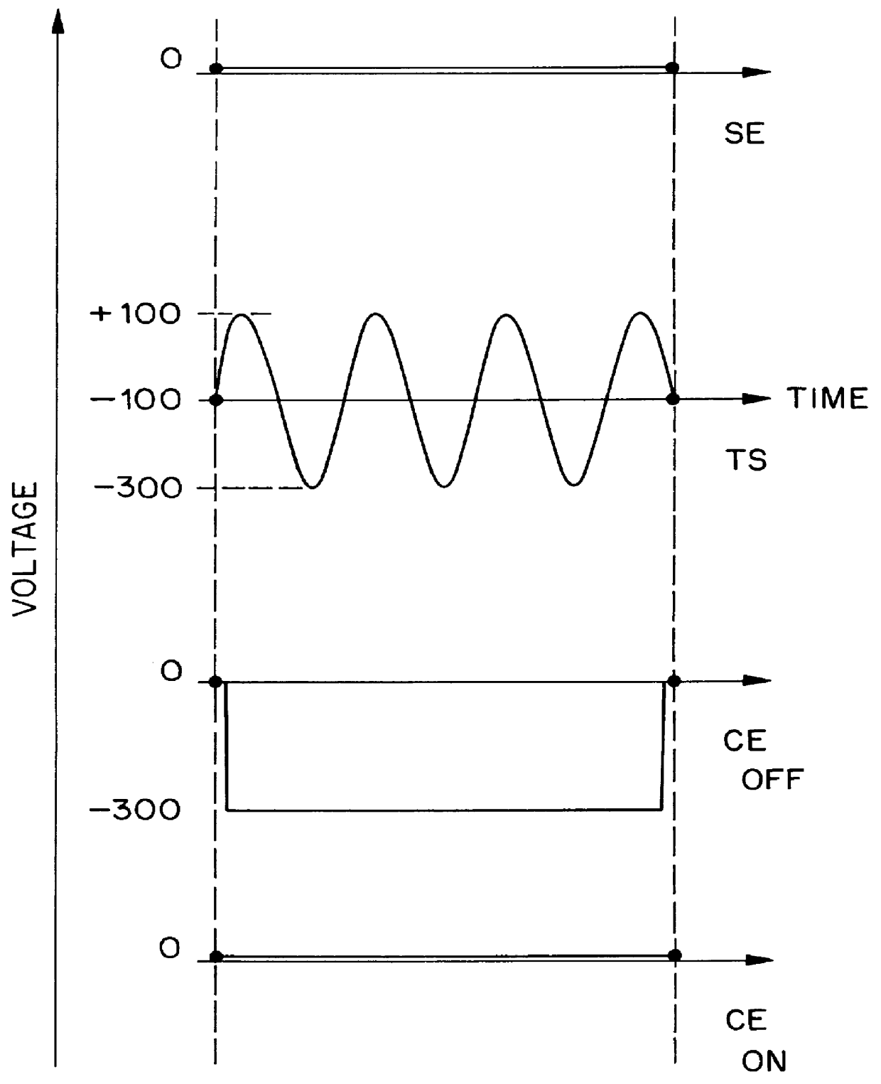
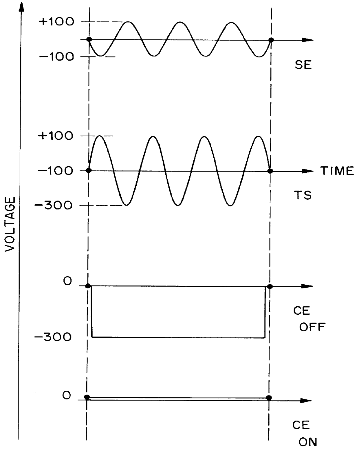
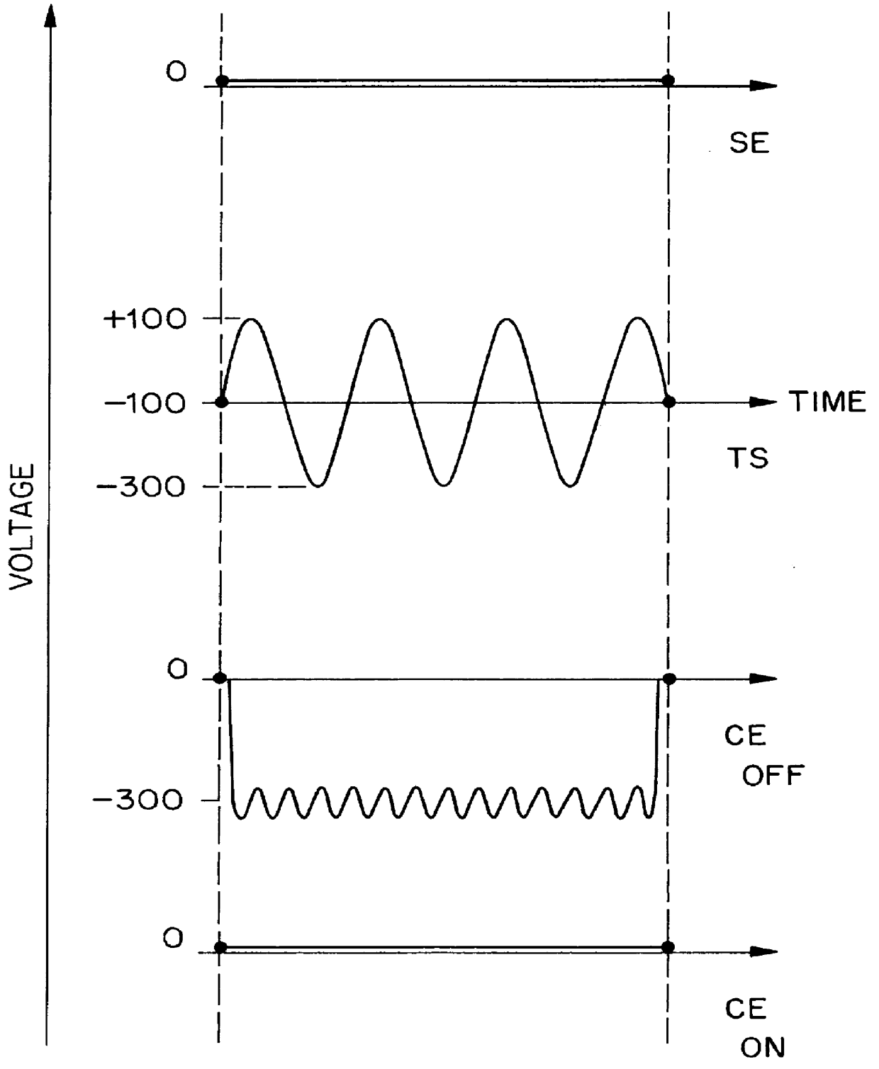
The same experiment as described in example 1 was repeated except that the toner delivery means was grounded and to the control electrodes a sinusoidally changing AC-field of 400 V (peak to peak) with -100 V DC offset (3 kHz) was used for pixels of maximum image density while only 0 V DC was used for pixels of minimum image density. Compared to example 1 only one AC signal was necessary and phase shifting compared to the AC applied towards the toner bearing surface, due to the capacitance of the different control electrodes, could not interfere. The maximum image density was lowered to 90% compared with example 1 but no missing lines nor toner accumulation upon said printhead structure could be observed.


PUM


Abstract

A direct electrostatic printing device includes a printhead structure with apertures and control electrodes associated with the apertures for delivering toner from a toner source to a substrate in accordance with image data. A first voltage source is provided to establish a flow of toner particles from the toner source to the substrate. A second voltage source is provided to establish a control voltage between the toner source and the control electrodes to control toner flow in accordance with the image data. The second voltage source provides a first AC field between a toner source and the control electrodes to permit toner flow and a second, diminished, AC field between the toner source and the control electrodes in order to stop the toner flow.

Description

This invention relates to a method and an apparatus used in the process of electrostatic printing and more particularly in Direct Electrostatic Printing (DEP). In DEP, electrostatic printing on an image receiving substrate is performed by creating a flow of toner particles from a toner bearing surface to the image receiving substrate and image-wise modulating the flow of toner particles by means of an electronically addressable printhead structure.In DEP (Direct Electrostatic Printing) the toner or developing material is deposited directly in an image-wise way on a receiving substrate, the latter not bearing any image-wise latent electrostatic image. The substrate can be an intermediate endless flexible belt (e.g. aluminium, polyimide etc.). In that case the image-wise deposited toner must be transferred onto another final substrate. Preferentially the toner is deposited directly on the final receiving substrate, thus offering a possibility to create directly the image on the final ...

Claims


Application Information

Patent Timeline
Patent Type & Authority Patents(United States)
IPC IPC(8): B41J2/41B41J2/415
CPCB41J2/4155G03G2217/0025
Inventor VAN GEMERT, DANNYPEYMEN, RAFLEONARD, JACQUESVAN DEN WIJNGAERT, HILBRANDDESIE, GUIDO
Owner AGFA GEVAERT AG
Why Eureka
Try Eureka