Damper device for mooring watercraft

a technology for mooring watercraft and mooring springs, which is applied in the direction of mooring equipment, towing/pushing equipment, vehicles/pulleys, etc., can solve the problems of easy deterioration effect of extending springs, noise of known devices, and easy deterioration of extending springs, etc., and achieve excellent resistance to deterioration effects

Inactive Publication Date: 2000-09-05
GIA FRA MA
View PDF3 Cites 26 Cited by
  • Summary
  • Abstract
  • Description
  • Claims
  • Application Information

AI Technical Summary

Benefits of technology

An object of this invention is to provide a damper device for watercraft which obviates the aforesaid drawbacks,

Problems solved by technology

The main drawback of known devices is their noise.
In this respect the rolling movement of the watercraft results in continuous stressing of the device, with consequent stressing of the spring which in extending or compressing to return to its rest position produces a very annoying noise.
It is well known that an extending spring is easily subject to yielding and, in the limit, to breakage due to excess load.
In the aforesaid known devices with an extending spring, this drawback is obviated or at least limited by the addition of a by-pass safety chain which however, when in operation, eliminates the damping effect with th

Method used


Image

  • Damper device for mooring watercraft
  • Damper device for mooring watercraft

Examples


Embodiment Construction

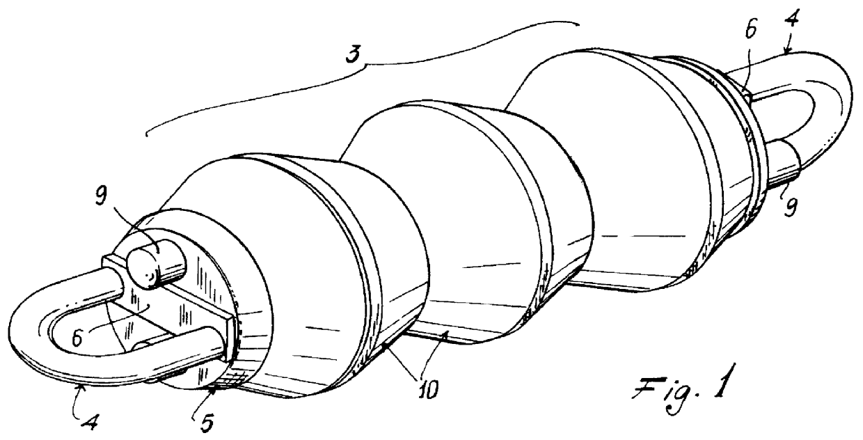
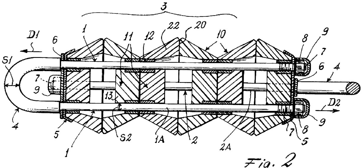
With reference to said figures, a device according to the invention comprises two U-bent elements 1 and 2, and a central elastic body 3 arranged to oppose the movement of the two elements 1, 2 in the opposing directions D1 and D2 respectively. In correspondence with their U-bent head 4 the rigid elements 1 and 2 comprise a disc 5 acting as an abutment for the elastic body 3, and having four equidistant holes for passage of the arms 1A, 2A of the elements 1 and 2.

Advantageously, the head 4 has a diameter S1 greater than the diameter S2 of the arms 1A, 2A. Furthermore, between the head 4 and the disc 5 there is fixed a spacer and stiffening bar 6. The free ends of the arms 1A, 2A have a threaded portion 7 to receive a nut 8 on which a protection cap 9 can be pressure-mounted.

In the illustrated example, the central elastic body 3 comprises six hollow, frusto-conical, circular-based members 10 of elastic plastic material open at their major base. In their minor base 11 these members com...


PUM


Abstract

A damper device for mooring watercraft, of the type comprising at least two rigid elements (1, 2), to one end of each of which there can be secured a mooring rope or chain, said elements being able to move coaxially in opposition to each other against the action of an elastic body (3) which comprises at least one member (10) constructed of an elastically deformable material.

Description

This invention relates to a damper device for mooring watercraft in accordance with the pre-characterising part of the main claim.In known devices of the aforesaid type the elastic element consists simply of a spring. The main drawback of known devices is their noise. In this respect the rolling movement of the watercraft results in continuous stressing of the device, with consequent stressing of the spring which in extending or compressing to return to its rest position produces a very annoying noise. It is well known that an extending spring is easily subject to yielding and, in the limit, to breakage due to excess load. In the aforesaid known devices with an extending spring, this drawback is obviated or at least limited by the addition of a by-pass safety chain which however, when in operation, eliminates the damping effect with the inevitable consequence that impact forces arise.It should also be noted that as said devices are constructed completely of rigid materials, they can...

Claims


Application Information

Patent Timeline
IPC IPC(8): B63B21/20B63B21/00F16F3/087F16F3/00
CPCB63B21/20F16F3/087B63B2021/005
Inventor BAJELI, MARIOPEDRUZZI, CARLO
Owner GIA FRA MA
Why Eureka
Try Eureka