D/A converter

a d/a converter and converter technology, applied in the field of oversampling d/a converters, can solve the problems of generating audible click noise, voltage vos of this dc offset at the output of d/a converters, and such drawbacks

Inactive Publication Date: 2000-09-05
KK TOSHIBA
View PDF7 Cites 30 Cited by
  • Summary
  • Abstract
  • Description
  • Claims
  • Application Information

AI Technical Summary

Problems solved by technology

However, there has been a following problem in the D/A converters shown in FIGS. 3 and 5.
That is, the D/A converters have had such a drawback that, if data being located near zero data are input into the .SIGMA.
However, a voltage Vos of this DC offset appears at the output of the D/A converter inevitably.
As a result, an audible cl

Method used


Image

  • D/A converter
  • D/A converter
  • D/A converter

Examples


first embodiment

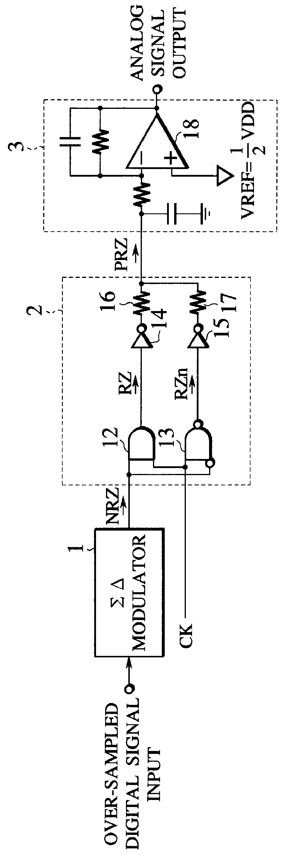
FIG. 12 is a block circuit diagram showing a configuration of an over-sampling D / A converter according to the present invention. Same references are labeled onto elements which are common to the related art described above. This D / A converter comprises an over-sampling filter 26, a .SIGMA. .DELTA. modulator 1, a PRZ (polar-return-to-zero) signal generator 2, and an analog filter 3.

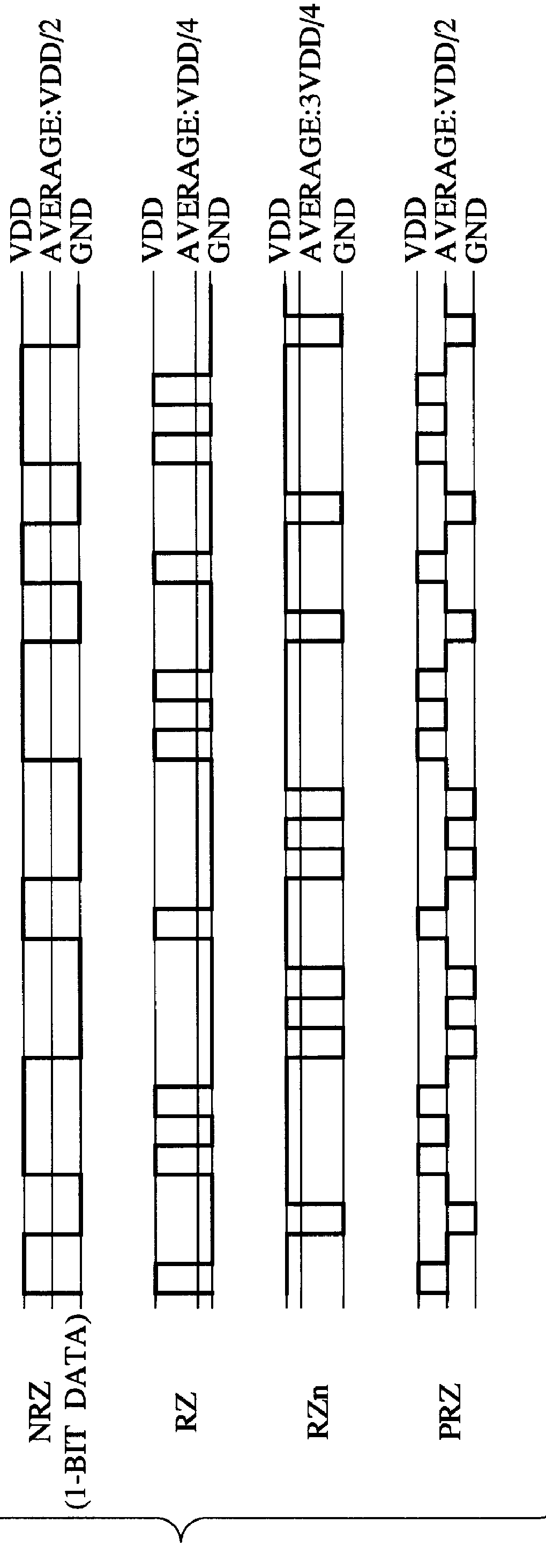
The over-sampling filter 26 receives a multibit digital signal input and then outputs a multibit over-sampled digital signal which is over-sampled at a frequency being n times (normally, n is 32 to 512) a sampling frequency. The .SIGMA. .DELTA. modulator 1 receives the multibit over-sampled digital signal from the over-sampling filter 26. Then, the .SIGMA. .DELTA. modulator 1 quantizes the received multibit over-sampled digital signal into one bit and then outputs an NRZ (non-return-to-zero) signal by one bit. FIG. 13 is a circuit diagram showing an example of a configuration of the .SIGMA. .DELTA. modulat...

second embodiment

(SECOND EMBODIMENT)

Next, a second embodiment of the present invention will be explained hereinbelow. FIG. 16 shows a configuration of an over-sampling D / A converter according to the second embodiment of the present invention. Same references are labeled onto elements which are common to the related art described above. In the second embodiment of the present invention, the RZ signal and the RZn signal being generated in the PRZ signal generator 2 in the first embodiment shown in FIG. 12 are replaced with each other. Like the above first embodiment, an effect of the resistor elements which are set to different resistor values will be explained hereinbelow. In this case, assume that the DC offset explained in FIG. 7 is also added onto the digital signal which is supplied to the .SIGMA. .DELTA. modulator 1.

If the similar consideration in the above first embodiment is applied, an output average DC potential E14 of the inverter circuit 14 obtained when the mute operation is OFF can be gi...

third embodiment

(THIRD EMBODIMENT)

Next, a third embodiment of the present invention will be explained hereinbelow. FIG. 19 shows a configuration of an over-sampling D / A converter according to the third embodiment of the present invention. Same references are labeled onto elements which are common to the related art described above. In the third embodiment of the present invention, this D / A converter comprises the .SIGMA. .DELTA. modulator 1, the PRZ signal generator 2, and the analog filter 3. In the D / A converter, an analog switch 22 for short-circuiting the feedback resistor element in the filter amplifier 18 is provided to the filter amplifier 18. Thus, an analog signal being output from the filter amplifier 18 can be fixed at a reference potential of the filter amplifier 18 by opening / closing the analog switch 22. FIG. 20 is a circuit diagram showing an example of a configuration of the analog switch 22 in FIG. 19. The analog switch 22 is composed of a transmission gate which is constructed by ...


PUM


Abstract

There is provided an over-sampling D/A converter which has a mute function for fixing an average DC potential of an analog output signal to a predetermined potential, and comprises a SIGMA DELTA modulator for receiving a multibit digital signal to which a DC offset value is added and then outputting a one-bit non-return-to-zero signal, a signal generator for receiving the non-return-to-zero signal and the clock signal, then generating a return-to-zero signal which is a logical multiplication of the non-return-to-zero signal and the clock signal and a complementary signal of the return-to-zero signal which is a logical addition of the non-return-to-zero signal and an inverted signal of the clock signal, and then adding the return-to-zero signal to the complementary signal of the return-to-zero signal to thus output a polar-return-to-zero signal, and an analog filter for receiving the polar-return-to-zero signal and then outputting an analog signal. Accordingly, because an average DC potential of an output signal at the time of the mute operation-ON is set substantially equal to the average DC potential of the output signal at the time of the mute operation-OFF, variation in the average DC potential in the output signal due to ON/OFF of the mute operation can be prevented. As a result, generation of audible click noises can be prevented.

Description

1. Field of the InventionThe present invention relates an over-sampling D / A converter for achieving a high S / N ratio and, more particularly, an over-sampling D / A converter which has a mute function at its output portion.2. Description of the Related ArtIn recent years, in the field of the D / A converter, an over-sampling D / A converter has been developed and employed in practical use. Such over-sampling D / A converter can achieve high conversion precision at a low conversion bit number based on the over-sampling technique in which a sampling frequency fs is set sufficiently higher than a signal frequency bandwidth fB. In particular, since the D / A converter using .SIGMA. .DELTA. modulation (sigma-delta modulation) can get a sufficient S / N ratio (signal-to-noise ratio) at a relatively low over-sampling ratio, recently such D / A converter has become the mainstream of the audio D / A converter.For example, followings may be listed as the over-sampling D / A converter. FIG. 1 is a block circuit ...

Claims


Application Information

Patent Timeline
IPC IPC(8): H03M3/02H03M3/04H03M1/08
CPCH03M3/348H03M3/50
Inventor NAGATA, MITSURU
Owner KK TOSHIBA
Why Eureka
Try Eureka