Overrunning coupling assembly

a coupling assembly and overrunning technology, applied in the direction of fluid couplings, gearing, interengaging clutches, etc., can solve the problems of noise generation, wear of the strut on the top and edge surfaces during overrunning, etc., to eliminate the requirement of lubrication control and reduce wear issues

Inactive Publication Date: 2000-09-12
MEANS IND INC
View PDF10 Cites 100 Cited by
  • Summary
  • Abstract
  • Description
  • Claims
  • Application Information

AI Technical Summary

Benefits of technology

The present invention improves upon prior overrunning coupling designs by providing enlarged strut pockets which allow radial sliding movement of the struts so that the struts may be supported by an inner or outer rail of the notch plate to prevent slapping of the struts against the notch recesses and to reduce wear issues and eliminate lubrication control requirements.

Problems solved by technology

For example, one potential problem associated with the above-referenced overrunning coupling design is that a certain amount of noise may be generated by the struts "slapping" or rattling against the notch recesses of the notch plate.
Also, wear of the strut on top and edge surfaces during overrun may be a concern.

Method used


Image

  • Overrunning coupling assembly
  • Overrunning coupling assembly
  • Overrunning coupling assembly

Examples


Embodiment Construction

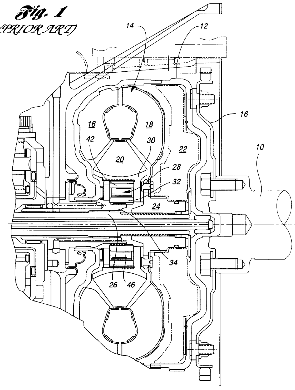
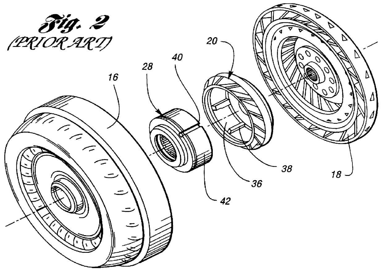
Shown in FIG. 1 is a prior art torque converter. An engine crankshaft 10 is connected drivably to impeller shell 12 of the hydrokinetic torque converter, generally identified by reference numeral 14. This connection is provided by drive plate 15. The impeller shell forms a part of a bladed impeller 16, which is arranged in a torque converter toroidal flow circuit partly defined by turbine 18. A bladed stator 20 is situated between the flow exit section of the turbine and the flow entrance section of the impeller. A torque converter lock-up clutch, not shown, would be located as shown in phantom at 22 in FIG. 1. This clutch, when it is applied, would connect the impeller with the turbine.

Turbine 18 includes a turbine hub 24 which is splined to turbine sleeve shaft 26. The torque input element of the planetary gearing (not shown) is connected drivably to the turbine sleeve shaft.

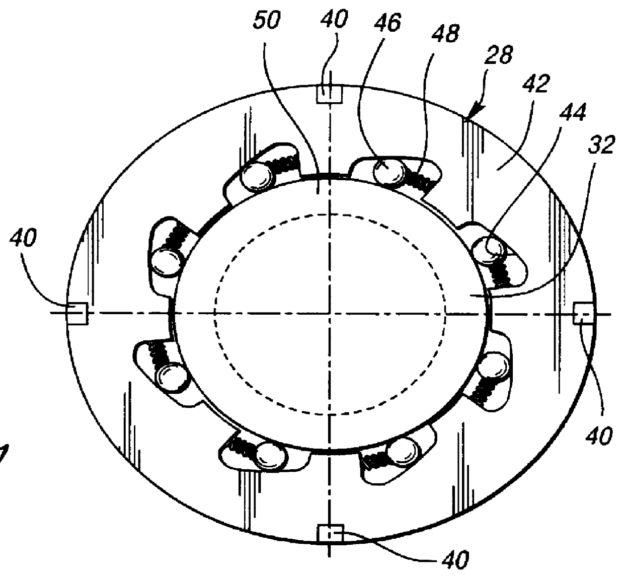
An overrunning coupling 28 of a conventional prior art design is disposed in the hub 30 of the stator 20. I...


PUM


Abstract

An overrunning coupling assembly includes a notch plate and an annular coupling pocket plate positioned in face-to-face relationship with respect to each other along a common axis. The pocket plate includes strut pockets disposed at angularly spaced positions about the axis. The notch plate includes notch recesses at angularly spaced positions about the common axis and positioned in juxtaposed relationship with respect to the strut pockets. The notch plate includes an inner circumferential rail at a radially inward side of the notch recesses and an outer circumferential rail at a radially outward side of the notch recesses. Torque-transmitting struts are positioned in the strut pockets. Each strut has first and second ears at one edge thereof for enabling pivotal motion of the struts about an ear axis intersecting the ears. The opposite edge of each strut is engageable with one of the notch recesses whereby one-way torque transfer may occur between the plates. Each opposite edge has first and second corners. Each strut pocket is sufficiently enlarged to allow pivotal movement of each strut about a strut axis which is parallel with the common axis, thereby enabling one of the first and second corners to be selectively supported by one of the inner and outer circumferential rails to prevent the struts from slapping against the notch recesses as the notch plate and pocket plate are respectively counterrotated.

Description

The invention relates to an overrunning coupling assembly including enlarged strut pockets so that the struts are radially movable to be supported on an inner or outer rail adjacent the notch recesses to prevent slapping of the struts against the notch recesses.The invention is adapted especially for use in stator assemblies for torque converter transmissions in an automotive vehicle driveline. The invention may be used also in other applications, however, such as torque transfer drives and chain drives that require an overrunning coupling in a torque flow path.Torque converter transmissions include a stator assembly having a stator hub secured to a stationary sleeve shaft and stator blades situated between a toroidal flow exit section of a hydrokinetic turbine and the toroidal flow entrance section of a hydrokinetic impeller. The blades of the stator change the direction of the tangential component of the toroidal flow velocity vector at the turbine exit section prior to entry of t...

Claims


Application Information

Patent Timeline
Patent Type & Authority Patents(United States)
IPC IPC(8): F16D41/00F16D41/12F16H41/24
CPCF16D41/125F16H2041/246
Inventor RUTH, STEPHEN M.
Owner MEANS IND INC
Why Eureka
Try Eureka