Optical-fiber polarimetric sensor

a polarimetric sensor and optical fiber technology, applied in the direction of optical conversion of sensor output, optical radiation measurement, instruments, etc., can solve the problems of inability to use electrical, capacitive or potentiometric type sensors, inability to use optical encoders, etc., and achieve the effect of improving the accuracy of measurement results

Inactive Publication Date: 2000-09-12
SN DETUDE & DE CONSTR DE MOTEURS DAVIATION S N E C M A
View PDF7 Cites 4 Cited by
  • Summary
  • Abstract
  • Description
  • Claims
  • Application Information

AI Technical Summary

Benefits of technology

The present invention thus proposes a novel optical-fiber polarimetric sensor making high-accuracy measurements possible and operating over a wide temperature range extending from cryogenic temperatures to high temperatures of about 400.degree. C., regardless of any parasitic disturbances to which it might be subjected.
An object of the invention is also to propose a sensor in which the packaging of the optical fiber is such as to contribute to making it insensitive to temperature. Another object of the invention is to provide a sensor which is particularly simple to assemble both optically and mechanically without requiring any optimization pre-adjustment on a test bench. Yet another object of the invention is to provide a sensor that can be implemented either as an angular position sensor or as a linear displacement sensor (after a simple transformation has been performed).
With the structure of the invention, any rigid contact between the measurement fiber and its supports is eliminated, thereby making the measurements totally independent of thermal stresses.

Problems solved by technology

In practice, methods of measuring position by taking direct measurements on devices, such as plug valves, immersed in a cryogenic fluid, make it impossible to use electrical, capacitive or potentiometric type sensors, in general, and also make it impossible to use optical encoders.
Such environments can be disturbed by temperature, by electromagnetic radiation, by high pressures, by vibration, and by the explosive nature of certain cryogenic fluids such as liquid hydrogen and oxygen.
The types of sensor that can be taken into consideration are thus limited by the constraints induced by such critical environments.
Unfortunately, in spite of its accuracy and its independence relative to electromagnetic disturbances, that type of optical-fiber sensor suffers from certain drawbacks, in particular because it is too sensitive to temperature and to pressure.

Method used


Image

  • Optical-fiber polarimetric sensor
  • Optical-fiber polarimetric sensor
  • Optical-fiber polarimetric sensor

Examples


second embodiment

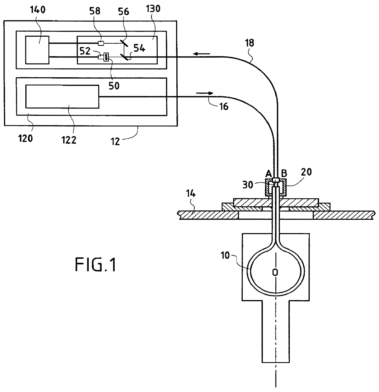
a sensor of the invention is shown in FIG. 7. This embodiment has a one-piece structure (without the emission and the detection being separate and at a distance). In this case, the go and return link fibers are no longer necessary since the measurement fiber is connected directly to the laser-emitter diode and to the detection means.

The sensor is made up essentially of the measurement fiber 10 which is connected directly to the optoelectronics box 12. As in the first embodiment, the optoelectronics box contains a temperature-stabilized optoelectronic component 122 acting as a monochromatic light source of determined polarization, e.g. a semiconductor laser diode mounted on a thermal-regulation Peltier element. A thermistor for measuring the temperature of the laser diode, and a photodiode for measuring the light intensity injected into the measurement fiber are, in principle, incorporated into the component. The box also contains the detection component 130 for detecting the measure...


PUM


Abstract

An optical-fiber polarimetric sensor for measuring the displacement of an object relative to a frame, the sensor comprising a measurement optical fiber secured, over a fraction of its length, both to a central point of the object and to first and second fixed points of the frame, means disposed at one end of the measurement fiber and serving to emit a light beam of determined polarization into said measurement fiber, means for exerting twist on the measurement fiber so as to modify the polarization of the light beam, and means disposed at another end of the measurement fiber and serving firstly to detect the resulting light beam and secondly to determine the displacement of the object by analyzing the polarization modified in this way, wherein said measurement fiber is stripped, over said fraction of its length, of the covering that imparts mechanical strength thereto, and it is slid into a deformable guide sheath fixed both to the rotary object and also to the frame. Preferably, the deformable guide sheath is made of fine steel, and it may lined with a flexible protective sheath.

Description

The present invention relates to an optical-fiber polarimetric position sensor for use in severe environments, in particular cryogenic environments.PRIOR ARTIn practice, methods of measuring position by taking direct measurements on devices, such as plug valves, immersed in a cryogenic fluid, make it impossible to use electrical, capacitive or potentiometric type sensors, in general, and also make it impossible to use optical encoders. Such environments can be disturbed by temperature, by electromagnetic radiation, by high pressures, by vibration, and by the explosive nature of certain cryogenic fluids such as liquid hydrogen and oxygen. The types of sensor that can be taken into consideration are thus limited by the constraints induced by such critical environments. Nevertheless, an example of a solution to those difficulties is given by the Applicant's Patent Application FR 93 15 289 which relates to an optical-fiber angular position sensor operating by birefringence.Unfortunately...

Claims


Application Information

Patent Timeline
Patent Type & Authority Patents(United States)
IPC IPC(8): G01B11/16G01D5/26G01D5/34
CPCG01B11/18G01D5/344
Inventor GAUMONT, ERICCLEMENT, MICHELCHAKARI, AYOUBMEYRUEIS, PATRICK
Owner SN DETUDE & DE CONSTR DE MOTEURS DAVIATION S N E C M A
Why Eureka
Try Eureka