
Torsional vibration damper

Inactive Publication Date: 2000-09-19
ZF FRIEDRICHSHAFEN AG
View PDF8 Cites 31 Cited by
  • Summary
  • Abstract
  • Description
  • Claims
  • Application Information

AI Technical Summary

Benefits of technology

The invention is based on the notion that this type of wear which occurs locally on the gear is reduced if a torsion transmission device including rotatably mounted roller bodies are used instead of intermeshing gearwheels for transmitting the torques. Although the roller bodies engage a toothing for the transmission of torques, they roll on this toothing. The rolling friction occurring between the individual elements of the gear arrangement cause comparatively low wear.
For simple mounting of the roller carrier on the second flywheel mass arrangement by means of a sliding bearing, a first rivet which is centered substantially relative to the second axis of rotation passes through the two U-legs and is surrounded by a first sliding bearing sleeve between the two U-legs.

Problems solved by technology

One disadvantage of the known torsional vibration damper is that, when a torque to be transmitted fluctuates only slightly around an average value, such as occurs when an automobile travels evenly at an essentially constant speed for relatively long periods of time, the relative rotary positions of the flywheel mass arrangements, coupled to one another via the planetary gear change over long periods of time.
In comparison with other teeth of the planetary gear, therefore, these individual teeth undergo substantially increased wear which may lead to the destruction of individual teeth of the planetary gear and consequently limits the useful life of the vibration damper.
The frictional contact of individual tooth flanks one on the other, which takes place under possibly high load and with constant back and forth movements, leads to the premature wear of said tooth flanks.
The rolling friction occurring between the individual elements of the gear arrangement cause comparatively low wear.
In this arrangement, the gear arrangement requires a particularly small amount of axial space.
This results in a particularly compact design.
Furthermore, the lubricant also supplies viscosity friction force which may brake movement of the third flywheel mass arrangement in relation to the second flywheel mass arrangement and thus contributes to damping torsional vibrations.

Method used


Image

  • Torsional vibration damper
  • Torsional vibration damper
  • Torsional vibration damper

Examples


Embodiment Construction

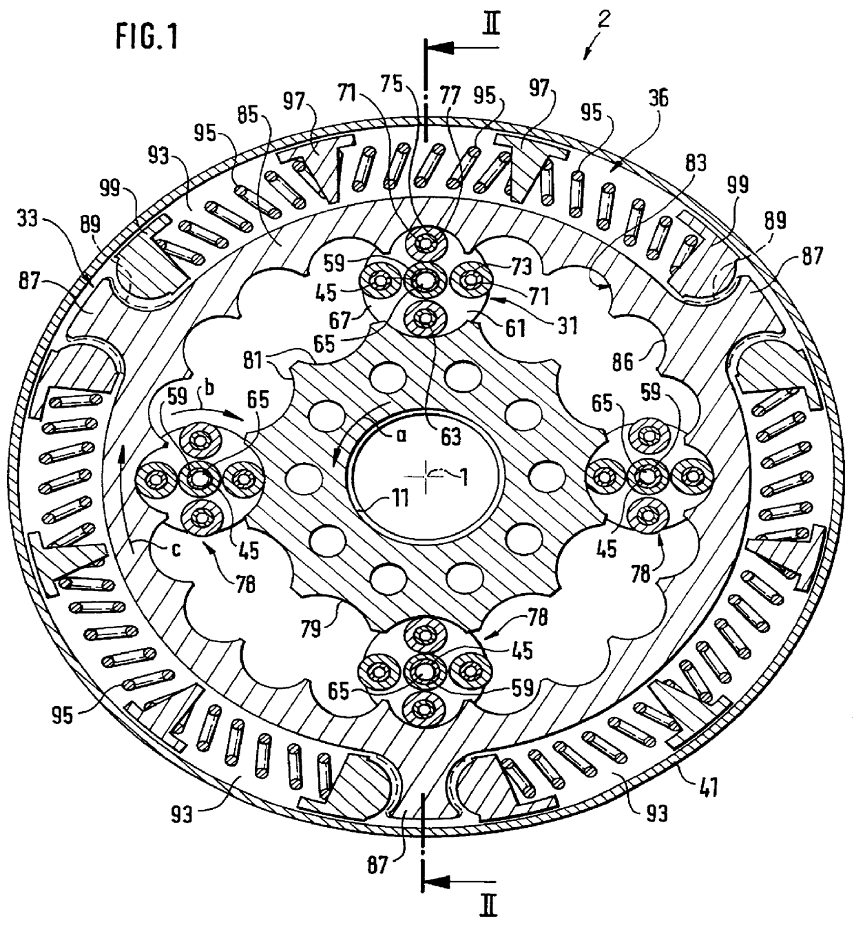
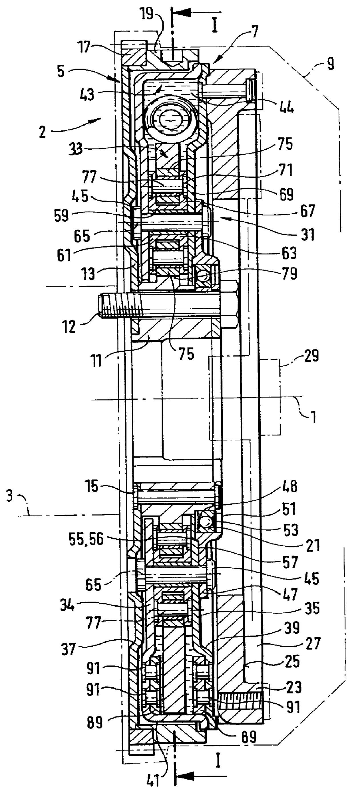
FIGS. 1 and 2 show sectional views of an embodiment of a torsional vibration damper 2 according to the present invention. The torsional vibration damper 2 is rotatable about an axis of rotation 1 and includes an input-side flywheel mass arrangement 5 connected to a crankshaft 3 and an output-side flywheel mass arrangement 7 which is arranged in a clutch housing 9 (the crankshaft 3 and clutch housing 9 are illustrated by dashed lines in FIG. 2). The input-side flywheel mass arrangement 5 comprises a central hub part 11 fastened to the crankshaft 3 by a plurality of circumferentially distributed screws 12 and an annular sheet metal form 13 extending essentially radially relative to the first axis of rotation 1. The radially inner circumference of the annular sheet metal form 13 is fastened to a side of the central hub part 11 axially facing the crankshaft 3 by a plurality of circumferentially distributed rivets 15. A starter gear ring 17 and a solid ring flywheel 19 are fixedly connec...


PUM


Abstract

A torsional vibration damper for arrangement in a drive train of an automobile comprises three flywheel mass arrangements arranged so as to be rotatable both jointly and relative to one another about a common first axis of rotation. At least two of the three flywheel mass arrangements are torsionally elastically coupled to one another by a spring arrangement. The three flywheel mass arrangements are coupled to one another via a roller gear. The first flywheel mass arrangement has a first toothing along at least a part circumference and the third flywheel mass arrangement has a second toothing along at least a part circumference. The second flywheel mass arrangement has at least one roller carrier mounted so as to be rotatable about a second axis of rotation and a plurality of roller bodies which roll on part regions of the first toothing and on part regions of the second toothing. Each roller body is arranged at a distance from the second axis of rotation and is mounted rotatably mounted on the roller carrier for rotating about a third axis of rotation assigned to the particular roller body.

Description

1. Field of the InventionThe invention relates to a torsional vibration damper for installation in a drive train of an automobile.2. Description of the Related ArtFor damping torsional vibrations in the drive train of an automobile, German Utility Model 94 14 314 discloses a torsional vibration damper comprising three flywheel mass arrangements which are arranged so as to be rotatable both jointly and relative to one another about a common first axis of rotation and which are coupled to one another by a planetary gear for the transmission of torsional forces. Two of the three flywheel mass arrangements are coupled to one another in a torsionally elastic manner by a spring arrangement. The first flywheel mass arrangement has an external toothing and comprises a sun wheel. Planet wheels which are rotatably mounted about second axes of rotation offset axially parallel to the first axis of rotation on the second flywheel mass arrangement are in meshed engagement with the external toothi...

Claims


Application Information

Patent Timeline
IPC IPC(8): F16F15/131F16F15/10F16F15/134F16F15/14
CPCF16F15/134F16F15/1478Y10T74/2131
Inventor DETTMAR, MARTIN
Owner ZF FRIEDRICHSHAFEN AG
Features
  • Generate Ideas
  • Intellectual Property
  • Life Sciences
  • Materials
  • Tech Scout
  • Unparalleled Data Quality
  • Higher Quality Content
  • 60% Fewer Hallucinations
Learn More