Electronically controlled engine mount

a technology of electric control and engine mount, which is applied in the direction of machine supports, shock absorbers, transportation and packaging, etc., can solve the problems of complex structure, difficult to put components into practical use, and high cost of components

Inactive Publication Date: 2000-09-19
DENSO CORP
View PDF20 Cites 32 Cited by
  • Summary
  • Abstract
  • Description
  • Claims
  • Application Information

AI Technical Summary

Problems solved by technology

Hei 4-39481 described above, respectively, those components are expensive and it has been difficult to put them into practical use.
Hei 6-330980, although an actuator of an electronically controlled engine mount has been constructed by using a voice coil having an inexpensive ferrite magnet, its structure is still complicated and it has been exp

Method used


Image

  • Electronically controlled engine mount
  • Electronically controlled engine mount
  • Electronically controlled engine mount

Examples


first embodiment

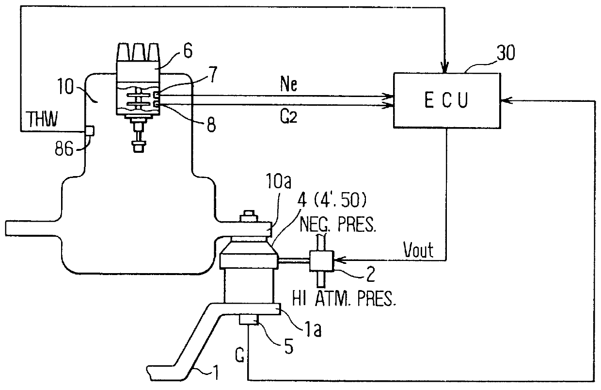
FIG. 1 is a schematic drawing showing a structure around an engine to which an electronically controlled engine mount of the present invention has been applied.

In FIG. 1, the electronically controlled engine mount includes an engine mount 4 disposed between a stay 1a of a body 1 and a stay 10a of an engine (internal combustion engine) 10, an ECU (Electronic Control Unit) 30 for controlling the engine mount 4, an acceleration sensor 5, attached on the stay 1a side of the body 1 near the engine mount 4, for outputting an acceleration signal G which corresponds to vibration generated by the body 1, a rotational angle sensor 7, disposed within a distributor 6 of the engine 10, for outputting a rotational angle signal N used to determine the engine speed, a reference position sensor 8 for outputting a reference position signal G2 related to a reference position of a crank angle and a water temperature sensor 86 for detecting temperature of engine cooling water. The rotational angle senso...

second embodiment

[Second Embodiment]

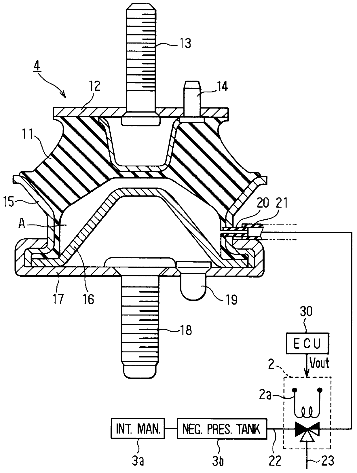
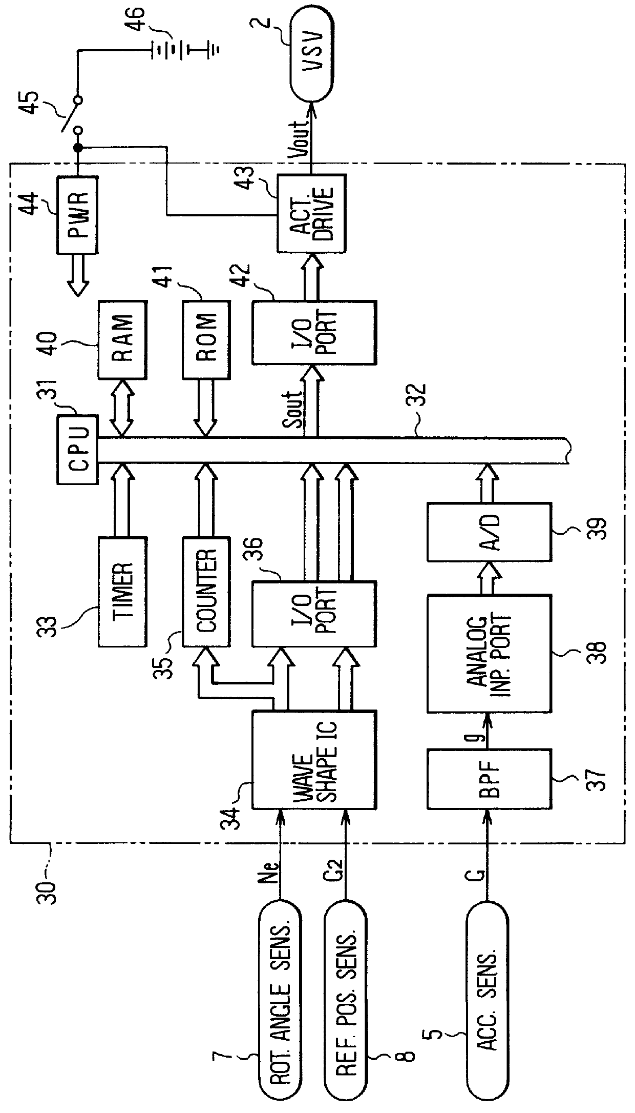
FIG. 7 is a cross-sectional view showing a detailed structure of an engine mount and peripheral devices thereof of the electronically controlled engine mount according to the second embodiment of the present invention. The engine and the peripheral devices thereof to which the electronically controlled engine mount of the second embodiment has been applied are the same as those shown in FIG. 1 in which the schematic structural drawing of the first embodiment is shown. Further, the block diagram in FIG. 3 showing the electrical structure of the first embodiment, the graphs in FIGS. 4A-4G showing each signal waveform and the flowchart in FIG. 5 are also the same, and therefore their explanation will be omitted here.

An engine mount 4' of the second embodiment adopts the known orifice liquid seal method and the structure thereof other than that is the same as the engine mount 4 of the first embodiment shown in FIG. 2. Accordingly, the present embodiment will be explai...

third embodiment

[Third Embodiment]

FIG. 8 is a cross-sectional view showing a detailed structure of an engine mount and peripheral devices thereof of the electronically controlled engine mount according to the third embodiment of the present invention. The engine and the peripheral devices thereof to which the electronically controlled engine mount of the third embodiment is applied are the same as those shown in FIG. 1 in which the schematic structural drawing of the first embodiment is shown. Further, the block diagram in FIG. 3 showing the electrical structure of the first embodiment, the graphs in FIGS. 4A-4G showing each signal waveform and the flowchart in FIG. 5 also apply here in the same manner and therefore, their explanation will be omitted here.

In FIG. 8, a fixing member 52 which protrudes upward to place and secure the engine 10 and which has a mounting hole 52a is embedded at the center of a mount rubber (rubber vibration isolator) 51 made of a thick elastic material of an engine mount...


PUM


Abstract

An engine mount which is capable of changing its vibration transmission characteristics with a simple structure using an inexpensive actuator is provided. A partition is inserted to a side member to which a mount rubber (rubber vibration isolator) of the engine mount is spliced to close a space between the mount rubber and to create an air chamber. An air duct pipe which communicates with the air chamber is connected to the side member and is connected to a VSV (vacuum switching valve) via a connection pipe. The VSV is controlled to ON/OFF states based on a driving voltage Vout from an ECU which corresponds to explosive vibrations of the engine to switch pressure within the air chamber to negative pressure of a vacuum tank in which negative pressure of an intake manifold is accumulated or to atmospheric pressure, interlocking with the vibration of the engine. Thereby, the vibration transmission characteristics of the engine mount may be adequately changed and the vehicular vibration may be reduced significantly.

Description

This application is related to Japanese Patent Application Nos. Hei 8-114986, 8-132478, 8-141300, 8-248354, and 9-27442, all of which are incorporated herein by reference.1. Field of the InventionThe present invention relates to an electronically controlled engine mount which is disposed between a body and an engine of a vehicle and which is capable of arbitrarily changing its vibration transmission characteristics in correspondence with a state of vibration of the engine.2. Description of Related ArtRecently, vibration transmission characteristics (e.g., dynamic spring constant and damping coefficient) of an engine mount has come to be electronically controlled to improve vehicular vibration characteristics. Japanese Utility Model Laid-Open Publication No. 4-39481 and Japanese Patent Application Laid-Open Publication Nos. Hei 4-185932, 5-306728, 6-330980 and 7-20439 disclose such devices.While an actuator of the electronically controlled engine mount has been constructed using a PZ...

Claims


Application Information

Patent Timeline
IPC IPC(8): F16F13/04F16F13/26
CPCF16F13/26
Inventor SHIBATA, AKIRAYAMAZOE, HISAMITSUHAYASHI, YOSHIHITOHONDA, KIYONARI
Owner DENSO CORP
Why Eureka
Try Eureka