Thermal sensing system having a fast response calibration device

a technology of thermal sensing and calibration device, which is applied in the field of thermal sensing system, can solve the problems of difficult system design, difficult adaptation to lightweight imager, and sensitive variation of transfer function from incident infrared flux to output signal (detector signal)

Inactive Publication Date: 2000-10-03
FLIR SYSTEMS TRADING BELGIUM BVBA
View PDF9 Cites 39 Cited by
  • Summary
  • Abstract
  • Description
  • Claims
  • Application Information

AI Technical Summary

Problems solved by technology

These systems are not easy to design however if compactness is important: the scanning mechanism renders the adaptation to lightweight imagers extremely difficult.
A major disadvantage of this system is that the transfer function from incident infrared flux to output signal (detector signal) is particularly sensitive to variation between detecting elements.
This results in an image degraded by fixed pattern noise arising from sources both within and independent of the detecting elements.
Additionally l / f noise introduces an error which increases with the period between calibrations.
The output from a staring array is thus of poor contrast in comparison.
However in such missiles the detector system is subject to rapid temperature change as the missile cone heats up during flight.
A disadvantage of such sensing systems is that possible reference temperature sources limit the performance in terms of speed and compactness.
If physically separate reference scenes are used then the sensor requires an optical system with considerable complexity and bulk.
Alternatively reference temperatures could be supplied by a Peltier cooled / heated reference plane but the finite time taken to adjust to temperature leads to a lengthy calibration process.
However this technique still requires mechanical movement mechanisms for both the disc spinning and scene scanning.
Overall, this imager is still bulky and unsuitable for some applications.
Furthermore there is a limit to the number of differing-reflectivity sections which can be incorporated on the disc.
One disadvantage of prior art thermal sensors is that detector nonuniformity is not linear over the temperature range of interest and making a nonlinear correction requires at least three reference scenes to emit radiation onto the detector.
In prior art imagers the settling time required by Peltier coolers prohibits such frequent checks and severe distortions can result with a high temperature scene.
Such a switching mechanism however is costly in terms of minimising system size.
Prior art sensors do not have this flexibility and reference temperature scenes may not bear any relation to a scene under observation and the calibration is therefore inaccurate.

Method used


Image

  • Thermal sensing system having a fast response calibration device

Examples


Embodiment Construction

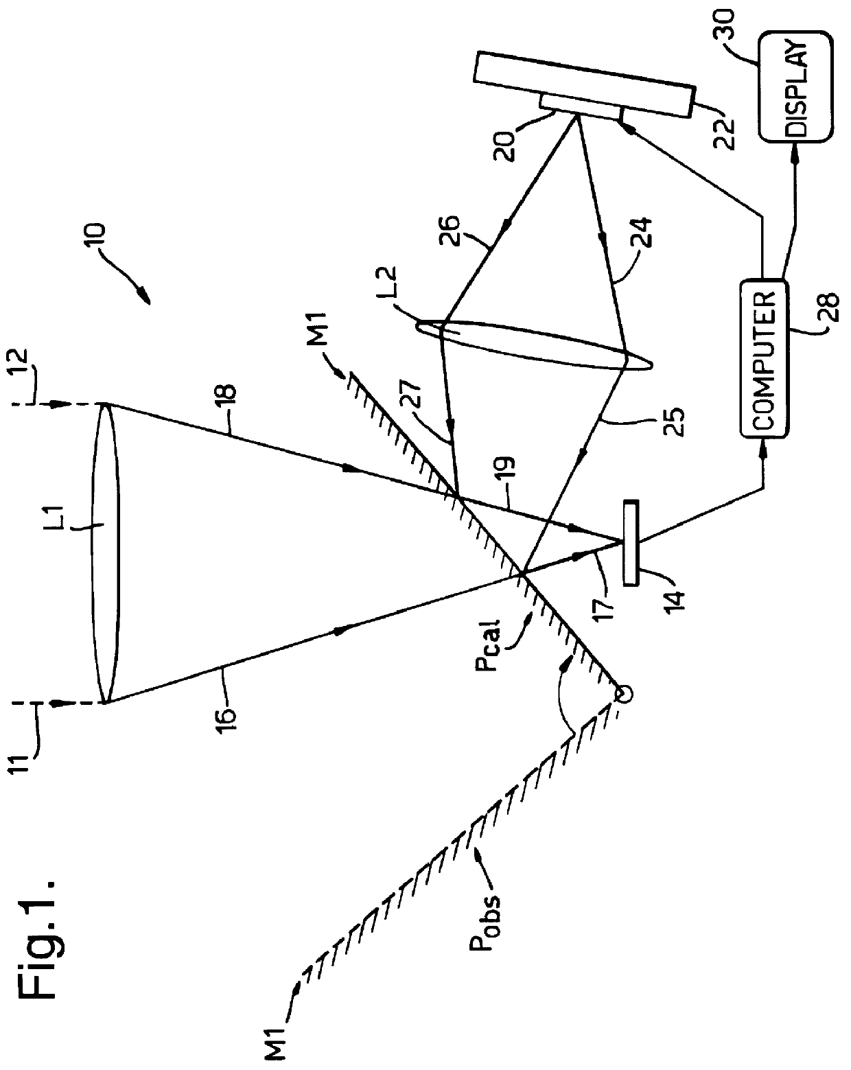
With reference to the FIGURE, there is shown a thermal sensing system in an imaging implementation indicated generally by 10. The system 10 incorporates an objective lens L1 which focuses infrared (IR) radiation, indicated by rays 11, 12, emanating from an observed scene (not shown) onto a two-dimensional array of microdetectors 14. A two-position mirror M1 is in either an observation position P.sub.obs (indicated by a dashed line) or a calibration position P.sub.cal (bold line). When the mirror M1 is in position P.sub.obs then the path of the radiation focused by the lens L1 corresponds to the region between the rays 16, 17 and 18, 19. An indium antimonide light emitting diode (LED) 20 is mounted on a Peltier cooler / heater device 22. A lens L2 passes IR radiation emitted by the LED 20 to the detector array 14 via reflection from the mirror M1 in its position P.sub.cal. The path followed by this radiation beam is contained within the rays 24, 25, 17 and 26, 27, 19. A computer 28 pro...


PUM


Abstract

PCT No. PCT/GB96/01805 Sec. 371 Date Jan. 9, 1998 Sec. 102(e) Date Jan. 9, 1998 PCT Filed Jul. 29, 1996 PCT Pub. No. WO97/05742 PCT Pub. Date Feb. 13, 1997A thermal sensing system (10) including an array of photon detectors (14) produces a detector-dependent response to irradiation. Variations in individual detector characteristics produce a fixed pattern noise which degrades an image or other response. A switchable mirror (M1) may at one position (Pcal) direct infrared radiation from a light emitting diode (20) onto the detector array (14). The diode (20) is both a negative and positive luminescent emitter, the flux emitted is current controlled to be equivalent to black body radiation at a range of temperatures both colder and hotter than ambient. Calibration relationships comprising transfer functions relating incident intensity to signal response are derived for each detector. Alternatively the mirror (M1) may be at an observation position (Pobs) and infrared radiation from a remote scene reaches the detector array (14). Resulting detector signals are converted into corrected fluxes using individual calibration relationships previously derived and an image or response with reduced fixed pattern noise is obtained.

Description

1. Field of the InventionThis invention relates to a thermal sensing system and more particularly to both imaging and non-imaging sensing systems incorporating an array of photon-detecting elements.2. Discussion of Prior ArtThermal imaging systems are known in the prior art. Such imaging systems can involve either series or parallel processing. In the former case a scene is scanned and each component of the scene is focused sequentially onto a detector. These systems are not easy to design however if compactness is important: the scanning mechanism renders the adaptation to lightweight imagers extremely difficult. An alternative arrangement for area imaging is to employ many detectors to sample simultaneously distinct sections of the scene. A major disadvantage of this system is that the transfer function from incident infrared flux to output signal (detector signal) is particularly sensitive to variation between detecting elements. This results in an image degraded by fixed pattern...

Claims


Application Information

Patent Timeline
Patent Type & Authority Patents(United States)
IPC IPC(8): H04N5/217H04N5/33G01J5/48H04N5/365
CPCH04N5/33H04N5/3651F41G7/2293F41G7/2253F41G7/001H04N25/671
Inventor ASHLEY, TIMOTHYELLIOTT, CHARLES TGORDON, NEIL THALL, RALPH S
Owner FLIR SYSTEMS TRADING BELGIUM BVBA
Why Eureka
Try Eureka