Image forming apparatus having a charging member applying an electric charge through electrically conductive or electroconductive particles to the surface of a photosensitive or image bearing member

a technology of image forming apparatus and charging member, which is applied in the direction of electrographic process apparatus, corona discharge, instruments, etc., can solve the problems of inability to completely eliminate the problems of -type charging apparatus, inability to avoid generating by-products of electrical discharge, and active ions such as ozone ions

Inactive Publication Date: 2000-10-03
CANON KK
View PDF18 Cites 91 Cited by
  • Summary
  • Abstract
  • Description
  • Claims
  • Application Information

AI Technical Summary

Problems solved by technology

Thus, in principle, when the electrical-discharge based charging system is in action, it is impossible to avoid generating the by-products of electrical discharge, that is, active ions such as ozone ions.
In reality, even a contact-type charging apparatus charges an object partially through the electrical-charge discharging system as described above, and therefore, a contact-type charging apparatus cannot completely eliminate the problems caused by the active ions such as ionized ozone.
However, in the case of this charging system, the state of the contact between a contact-type charging member and an object to be charged greatly affects the manner in which the object is charged, since this charging system is such a system that directly charges an object.
As a result, problems occur: absolute charging performance declines, the state of the contact between the charge roller and the photosensitive drum becomes less desirable, and foreign matter adheres to the charge roller and / or the photosensitive member.
However, prior to the present invention, even with the use of the DC charging method, it was difficult to bring the potential level of a photosensitive member exactly to a target level, since the resistance value of a contact charging member changed due to changes in ambience or the like, and also the threshold voltage Vth changed as the photosensitive member was shaved away.
Further, when AC voltage is used so that an object is uniformly charged due to the averaging effect of AC voltage, the problems related to AC voltage become more conspicuous.
For example, more ozone is generated; noises associated with the vibration of the contact-type charging member and the photosensitive drum caused by the electric field of AC voltage increase; and the deterioration of the photosensitive member surface caused by electrical discharge increases, which add to the prior problems.
In terms of fiber density, pile with a density of 100 fiber / cm.sup.2 can be relatively easily obtained, but the density of 100 fiber / cm.sup.2 is not sufficient to create a state of contact which is satisfactory to directly charge an object.
Therefore, the fur brush type charging device is not practical.
However, a magnetic-brush-type charging apparatus also has its own problems.
For example, it is complicated in structure.
Thus, even this contact-type charging apparatus is liable to cause problems; for example, images are affected by ozonic products, appearing as if flowing, when this charging apparatus is used for an extended period of time, in particular, when this charging apparatus is used in a cleanerless image forming apparatus for an extended period of time.
2) When a contact-type charging apparatus is employed as a means for charging the image bearing member of an image forming apparatus which employs a toner recycling process, there is no cleaner for removing the toner which remains on the peripheral surface of the image bearing member after image transfer.
As a result, the residual toner contaminates the contact-type charging member, interfering with the process through which charge is directly injected from the contact-type charging member to the image bearing member, or making it practically impossible for the image bearing member to be directly charged by the contact-type charging member.
If the amount of the charge which the image bearing member receives is insufficient, the amount of the toner which adheres to the contact-type charging member increases, interfering further with the charging of the image bearing member, and therefore, perpetuating this undesirable cycle.
However, also in this case, an image bearing member is primarily charged through electrical discharge, and therefore, there are problems similar to those described above.
Neither state creates a problem.
In other words, it takes too much torque to drive them.
Further, the extremely small amount of the charge facilitator particles m fails to sufficiently improve the state of contact between the charge roller 2 and the photosensitive member 1, and therefore, the improvement in the charging performance of the apparatus is not sufficient.
On the other hand, if the amount of the charge facilitator particles m between the charge roller 2 and the photosensitive member 1 is extremely large, too many charge facilitator particles m fall off from the charge roller 2, which sometimes has detrimental effects on image formation.
If it is less than 10.sup.3 particle / mm.sup.2, the lubricative effect, and the improvement in the state of contact between the charge roller 2 and the photosensitive member 1, are not sufficient, and therefore, the improvement in the charging performance is not as much as expected.

Method used


Image

  • Image forming apparatus having a charging member applying an electric charge through electrically conductive or electroconductive particles to the surface of a photosensitive or image bearing member
  • Image forming apparatus having a charging member applying an electric charge through electrically conductive or electroconductive particles to the surface of a photosensitive or image bearing member
  • Image forming apparatus having a charging member applying an electric charge through electrically conductive or electroconductive particles to the surface of a photosensitive or image bearing member

Examples


embodiment 1

In the case of Embodiment 1, in which the charge facilitator particles m were mixed in the developer 4d, the charge roller is continuously supplied with the charge facilitator particles m at a constant rate by way of the photosensitive member. Therefore, the desirable state of contact in terms of the charging of the photosensitive drum was maintained between the charge roller and the photosensitive member. When the peripheral velocities of the photosensitive drum and the charge roller were both increased, the photosensitive member was desirably charged, but when the peripheral velocity of the charge roller was reduced, the photosensitive member was slightly insufficiently charged. This proves that the photosensitive member is more efficiently charged when the peripheral velocity of the charge roller is rendered different from that of the photosensitive member.

In the case of the Embodiment 2, in which the electrical resistance of the surface layer of the photosensitive member was low...

embodiment 3 (fig.4)

Embodiment 3 (FIG. 4)

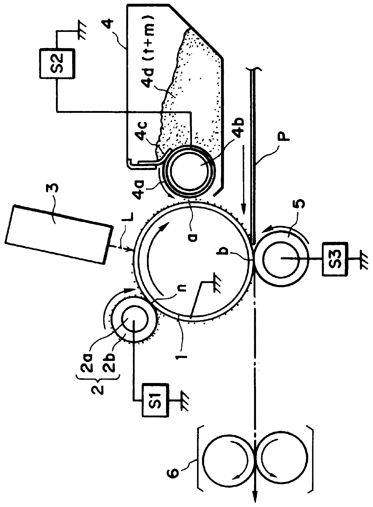
FIG. 4 is a schematic section of a typical image forming apparatus in accordance with the present invention.

The image forming apparatus described in this embodiment is a laser beam printer (recording apparatus) which employs a transfer-type electrophotographic process, a direct charging system, and a toner recycling process (cleanerless system).

(1) General structure

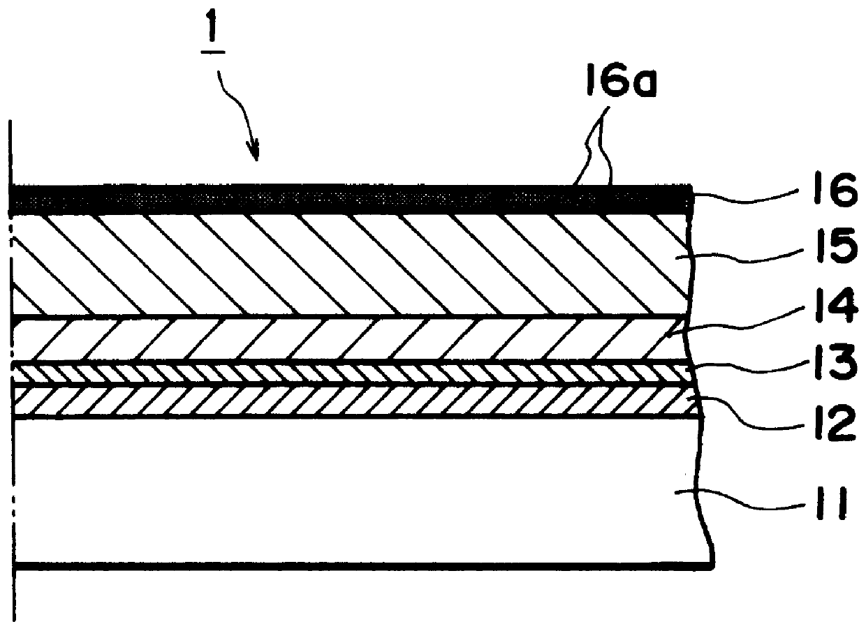
A reference numeral 1 designates a photosensitive member as an image bearing member, which is an organic photoconductor type member (negatively chargeable photosensitive member). It is in the form of a cylindrical drum with a diameter of 30 mm, and is rotatively driven in clockwise direction indicated by an arrow mark at a peripheral velocity of 94 mm / sec (process speed).

Designated by a reference numeral 2 is an electrically conductive elastic roller (hereinafter, "charge roller").

The charge roller 2 is formed by covering the peripheral surface of a metallic core 2a with a layer 2b of foamed material ...

embodiments 4 and 5

These embodiments are the same as Embodiment 3, except that a contact-type developing apparatus, which has a distance of 100 .mu.m between the development sleeve 4a and the photosensitive member 1, is employed in place of the developing apparatus 4 employed in Embodiment 3.

In Embodiment 4, the development bias is provided by the application of a DC voltage of -420 V. In Embodiment 5, the development bias is provided by the application of a compound voltage composed of a DC voltage of -420 V and an AC voltage with a frequency of 1600 Hz, a peak-to-peak voltage of 1600 V, and a rectangular waveform. Otherwise, the printer structure is the same as that in Embodiment 3.


PUM


Abstract

An image forming apparatus includes an image bearing member with a recirculatively movable peripheral surface; and a device for forming electrostatic latent images on the peripheral surface of the image bearing member, the device including a charging member to which voltage is applicable to charge the image bearing member. The charging member includes a flexible member capable of forming a nip between itself and the image bearing member; a developer for developing the latent image with the use of developer composed of toner particles and electrically conductive particles. The developer is capable of cleaning the residual toner particles from the image bearing member. The electrically conductive particles transferred onto the image bearing member by the developer are delivered to the nip by the image bearing member. The flexible member is moved so that it maintains a peripheral velocity difference relative to the image bearing member.

Description

FIELD OF THE INVENTION AND RELATED ARTThe present invention relates to image forming apparatuses such as copy machines or printers.More specifically, the present invention relates to image forming apparatuses compatible with contact-type charging systems, transfer type systems, and toner recycling systems.Prior to the present invention, a corona type charger (corona discharging device) has been widely used as a charging apparatus for charging (inclusive of discharging) an image bearing member, such as an electrophotographic photosensitive member or an electrostatic dielectric recording member, to a predetermined polarity and a predetermined potential level in an image forming apparatus, for example, an electrophotographic apparatus or an electrostatic recording apparatus.The corona type charging device is a noncontact-type charging device, and comprises a corona discharging electrode, such as a wire electrode, and a shield electrode, which surrounds the corona discharging electrode....

Claims


Application Information

Patent Timeline
Patent Type & Authority Patents(United States)
IPC IPC(8): G03G15/02
CPCG03G15/0216G03G15/0241G03G2221/0005
Inventor CHIGONO, YASUNORINAGASE, YUKIOISHIYAMA, HARUMIHIRABAYASHI, JUN
Owner CANON KK
Why Eureka
Try Eureka