Susceptor for vapor-phase growth apparatus

Inactive Publication Date: 2000-10-10
SUMITOMO MITSUBISHI SILICON CORP
View PDF8 Cites 91 Cited by
  • Summary
  • Abstract
  • Description
  • Claims
  • Application Information

AI Technical Summary

Benefits of technology

All of the forgoing have resulted in a requirement for improvement of the apparatus of the present invention in which it is an objective of the present invention to provide a susceptor which can prevent the increasing phenomenon of the dopant concentration in the epitaxial layer at its peripheral portion, as it would b

Problems solved by technology

As a result, a particular region of the epitaxial layer where the dopant concentration is out o

Method used


Image

  • Susceptor for vapor-phase growth apparatus
  • Susceptor for vapor-phase growth apparatus
  • Susceptor for vapor-phase growth apparatus

Examples


Embodiment Construction

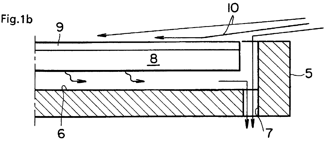
Using the horizontal single wafer type vapor-phase growth apparatus with a lamp-heating method as seen in FIG. 1, an epitaxial film with the film thickness of about 10 pm was formed at a reaction temperature of 1,150.degree. C. onto the P++ type (100) plane silicon semiconductor base plate (with 200 mm diameter) having the specific resistance of 5 m.OMEGA.cm using SiHCl.sub.3 diluted with hydrogen as the silicon supplying source gas. Two tests were conducted; one was with susceptor having the through-hole of the present invention and the other was with the conventional type of susceptor without any through-holes as seen in FIG. 3.

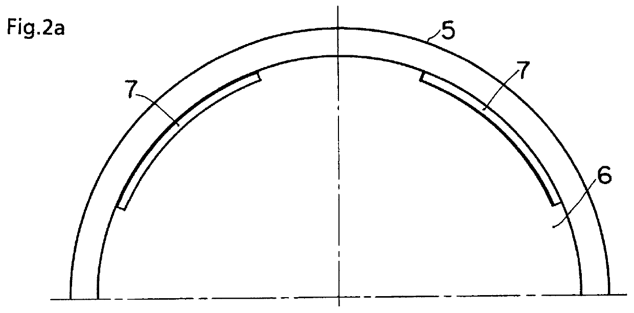
As seen in FIGS. 2a and 2b, the suscpetor according to the present invention has an arcshaped groove-type through-hole portion 7 at the most outer peripheral portion of the wafer pocket 6. In FIG. 2a, four locations are installed with the through-hole portions 7 leaving the connecting area of 75 mm on its peripheral portion. On the other hand, in FIG. 2b, f...


PUM

PropertyMeasurementUnit
Concentrationaaaaaaaaaa

Abstract

It was an objective of the present invention to provide a susceptor which can prevent a increasing phenomenon of the dopant concentration of the epitaxial layer at the peripheral portion of the wafer. By providing a through-hole 7 passing through to a rear side at the outer peripheral side of the wafer inside the wafer pocket 6, a down flow of a reacting source gas from the upper surface of the susceptor 5 is formed, so that the unwanted flow of the dopant species being exhausted at the rear surface onto the wafer surface can be avoided. As a result, a raise in the dopant concentration at the outer peripheral portion of the epitaxial layer 9 can be controlled.

Description

1. Field of the InventionThe present invention relates to an improvement of a susceptor which is employed to a vapor-phase growth apparatus to grow an epitaxial film onto the semiconductor wafer. More specifically, the present invention relates directly to a vapor-phase growth apparatus in which a through-hole portion extending to a rear side of the susceptor is provided at the most outer peripheral portion inside the wafer pocket in order to mount the wafer, and a raise in dopant concentration at the outer periphery of the grown epitaxial film can be controlled.2. Description of the Prior ArtAs to a vapor-phase growth apparatus in order to grow an epitaxial film onto the semiconductor wafer, there have been several conventional types of apparatus available; they may include (1) a vertical-type vapor-phase growth apparatus in which the susceptor being placed on a circular disc is heated from its bottom side, and (2) a single wafer type vapor-phase growth apparatus with which a good ...

Claims


Application Information

Patent Timeline
IPC IPC(8): C23C16/44C30B25/12C23C16/458C30B25/14C23C16/455H01L21/205H01L21/683
CPCC23C16/4412C30B25/14C30B25/12C23C16/4583
Inventor NAKAMURA, OSAMU
Owner SUMITOMO MITSUBISHI SILICON CORP
Why Eureka
Try Eureka