Nozzle for use in a torch head of a plasma torch apparatus

a plasma torch and nozzle technology, which is applied in the direction of plasma welding apparatus, electrical apparatus, arc welding apparatus, etc., can solve the problems of insufficient or inhomogeneous unsatisfactory residues or deposits of molten material, and insufficient cooling of the nozzle body. , to achieve the effect of improving the homogeneity of the cooling of the nozzle body member

Inactive Publication Date: 2000-10-24
SULZER METRO AG
View PDF10 Cites 51 Cited by
  • Summary
  • Abstract
  • Description
  • Claims
  • Application Information

AI Technical Summary

Benefits of technology

Thus, it is an object of the invention to provide a nozzle as well as a nozzle assembly for use in a torch head of a plasma torch apparatus that has an improved an more homogenous cooling of the nozzle body member. It is a further object of the invention to provide a nozzle as well as a nozzle assembly for use in a torch head of a plasma torch apparatus in which the danger of deposit build-up in the interior of the nozzle body is avoided.
Due to the fact that the cooling channels continue in axial direction throughout the nozzle body member up to the outlet region of the nozzle, and further due to the fact that the powder supply channels run between the cooling channels radially through the nozzle body member, both a uniform cooling of the nozzle up to its outlet region is ensured and an improved cooling of the powder supply channels is achieved.

Problems solved by technology

There is a danger associated with such anode nozzles insofar as the nozzle heats up in the region of the powder supply channel to such an extent that the coating powder is molten already in the interior of the powder supply channel, resulting in undesired residues or deposits of molten material.
Moreover, from time to time, such deposits become loose and are entrained with the plasma jet, with the result that they are deposited as clottings on the substrate to be coated.
Another problem arising in anode nozzles of the kind referred to herein may be seen in the fact that the nozzle body is insufficiently or inhomogenously cooled.
Particularly in the region of the outlet end of the nozzle body, the anode nozzle known in the art are insufficiently cooled because the cooling channels thereof are not led up to the outlet end of the nozzle body.

Method used


Image

  • Nozzle for use in a torch head of a plasma torch apparatus
  • Nozzle for use in a torch head of a plasma torch apparatus
  • Nozzle for use in a torch head of a plasma torch apparatus

Examples


Embodiment Construction

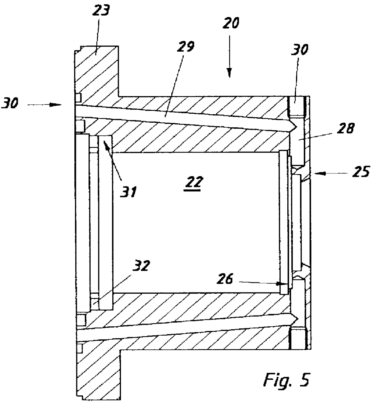
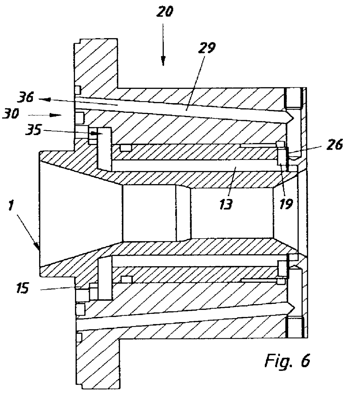
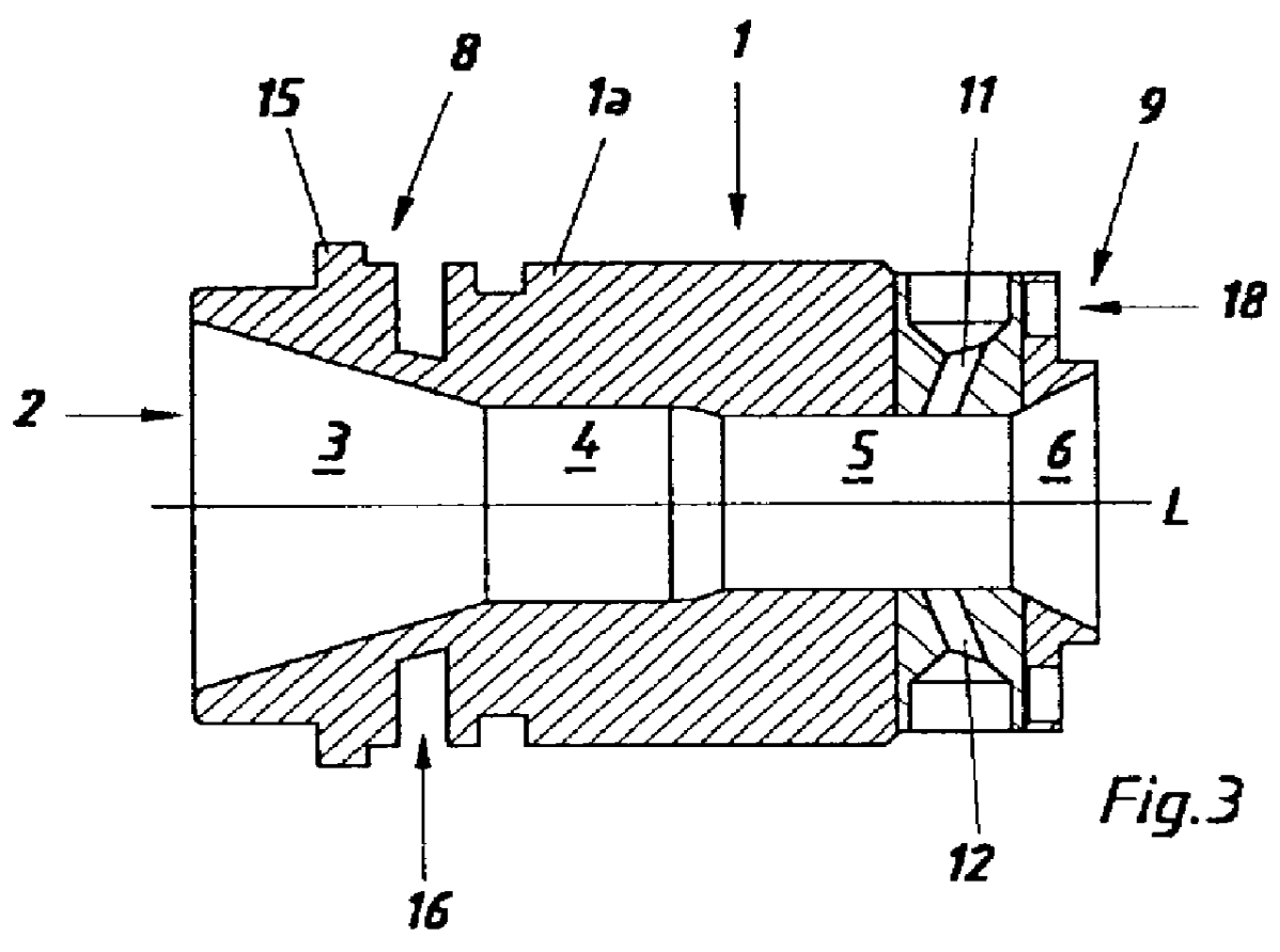
FIGS. 1-4 show an embodiment of a nozzle 1 for use in the torch head of a plasma torch apparatus in a front elevational view, in a cross sectional view, and in two different longitudinal sectional views. In the following, the design of that nozzle 1 shall be further explained, with reference to the above mentioned drawing figures. In view of the fact that the general design and function of such nozzles are well known to any person skilled in the art, only those characteristics of the nozzle 1 will be discussed in detail that are essential in connection with the present invention.Moreover, it is assumed that the nozzle 1 shall serve as an anode for creating a plasma torch and that the plasma gas flows through the nozzle 1, as seen in FIGS. 3 and 4, from the left side to the right side.

As can be seen from FIGS. 1 and 2, the nozzle 1 comprises a nozzle body member 1a of essentially cylindrical configuration that is provided with a central opening 2 as well as with a plurality of coolin...


PUM

PropertyMeasurementUnit
shapeaaaaaaaaaa
dimensionaaaaaaaaaa
meltingaaaaaaaaaa

Abstract

The nozzle is provided with a plurality of cooling channels running from an annular channel located in an inlet region of the nozzle through the nozzle in longitudinal direction up to an outlet region of the nozzle. The powder supply channels provided for the supply of coating material are led between the cooling channels. A nozzle support member adapted for receiving the nozzle is provided with cooling ducts that are hydraulically connected to the cooling channels of the nozzle and constitute therewith a nozzle cooling circulation system. The advantages of this design can be seen in the facts that the nozzle is homogeneously and efficiently cooled up to its outlet end and that the danger of building-up molten deposits within the nozzle is substantially avoided.

Description

The present invention refers to a nozzle for use in a torch head of a plasma torch apparatus, comprising a nozzle body member of essentially cylindrical configuration having a central longitudinal axis, an opening running through the nozzle body member, located coaxially with the central longitudinal axis, and having an inlet end and an outlet end, and a plurality of cooling channels running through the interior of the nozzle body member and arranged symmetrically around the central longitudinal axis. Moreover, the present invention refers to a nozzle assembly for use in a torch head of a plasma torch apparatus, comprising a nozzle as referred to herein above as well as a nozzle supporting member.PRIOR ARTNozzles for use in the torch head of a plasma torch apparatus, i.e. a so-called plasma gun, are known in the prior art in a wide variety of designs and constructions. Such nozzles, on the one hand, serve for concentrating the plasma stream in a desired manner and, on the other hand...

Claims


Application Information

Patent Timeline
Patent Type & Authority Patents(United States)
IPC IPC(8): H05H1/28H05H1/26H05H1/34B23K10/00H05H1/42
CPCH05H1/28H05H2001/3478H05H1/3478
Inventor KELLER, SILVANO
Owner SULZER METRO AG
Why Eureka
Try Eureka